LG 65NANO80ASA
Сервис мануал для LG 65NANO80ASA
Размер файла: (3.24 mb)Производитель: SIS
Просмотров: 24
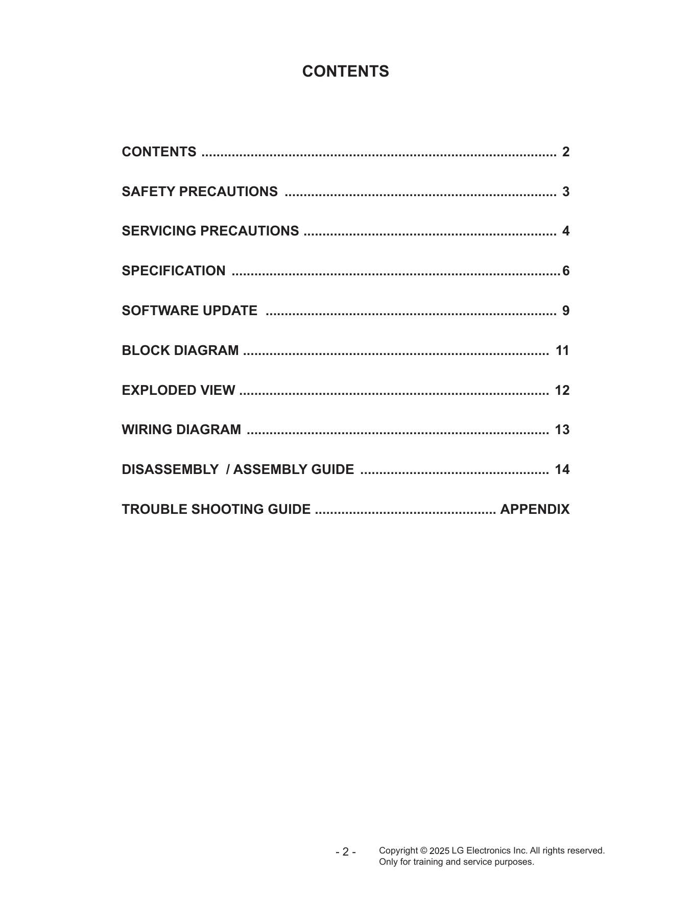
- руководство по ремонту (сервис-мануал)
Сервис мануал для LG 65NANO80ASA
Размер файла: (3.24 mb)
Руководство пользователя для LG 65NANO80ASA