LG OLED65G2
- руководство по ремонту (сервис-мануал)
Текст из PDF
НОВОЕ
Скриншоты PDF
Извлечено автоматически
СТРАНИЦА PDF
Страница 1
Все сервис мануалы для телевизоров LG: http://webos-forums.ru/topic3291.html
СТРАНИЦА PDF
Страница 2
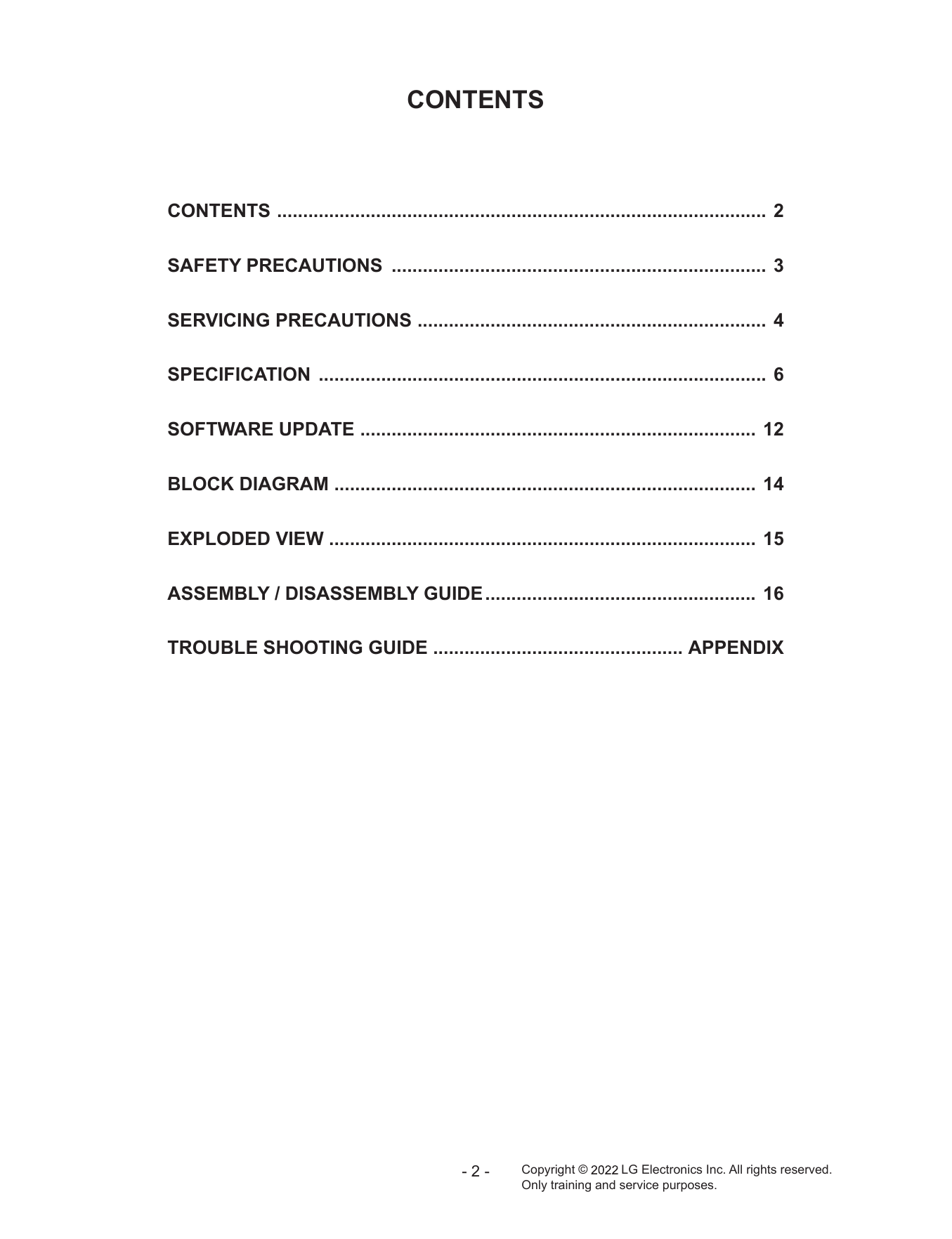
CONTENTS
СТРАНИЦА PDF
Страница 3
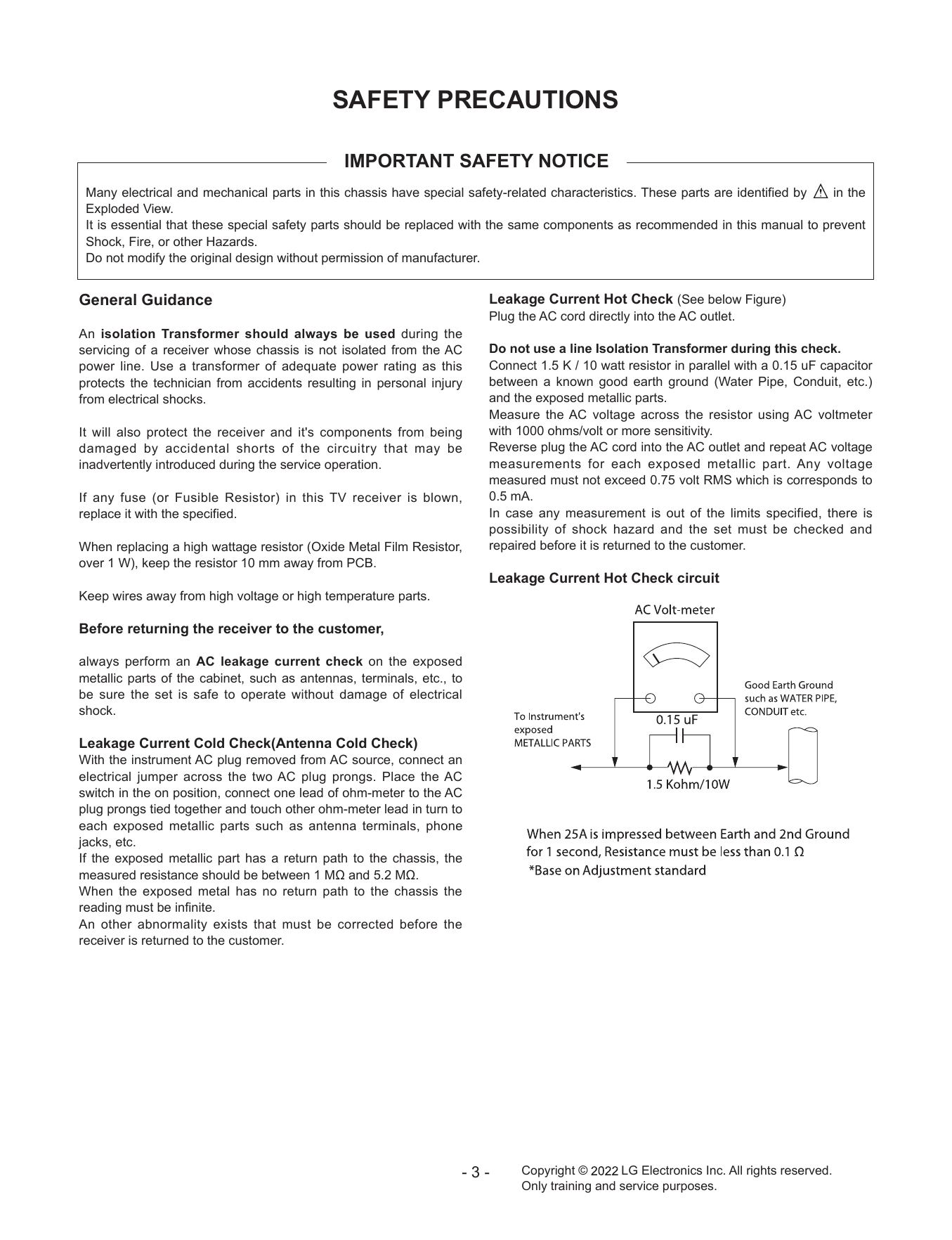
SAFETY PRECAUTIONS
СТРАНИЦА PDF
Страница 4
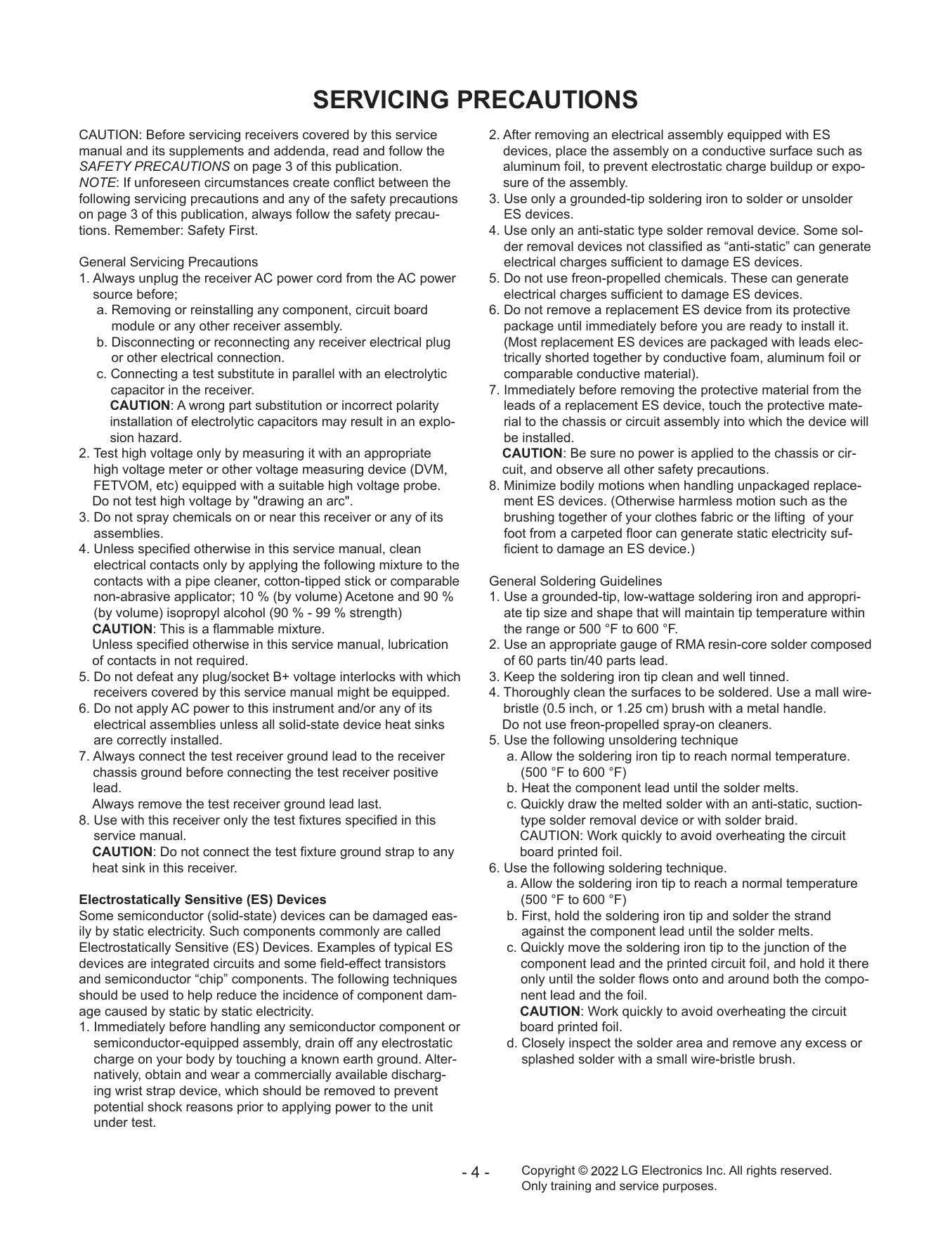
SERVICING PRECAUTIONS
СТРАНИЦА PDF
Страница 5
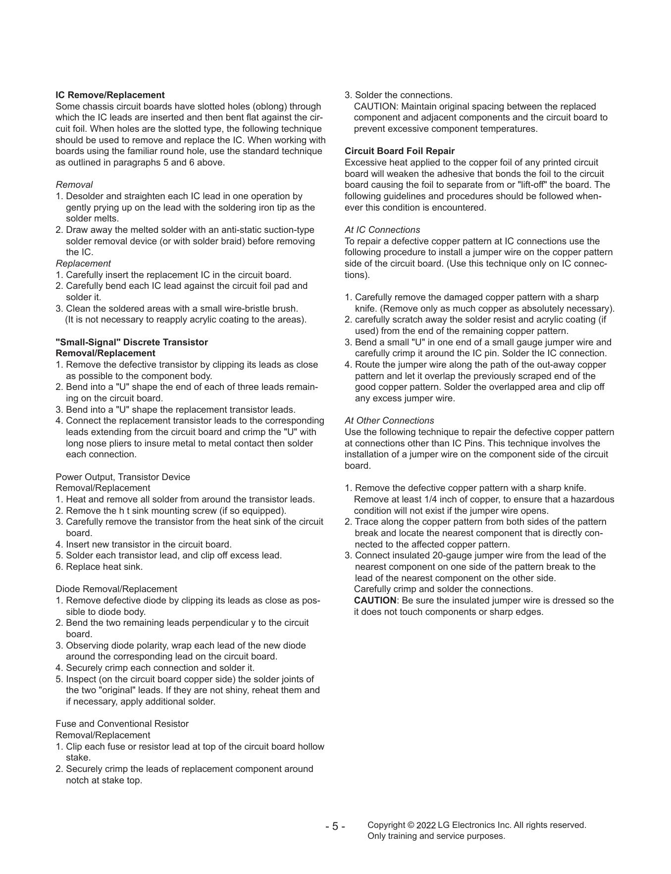
IC Remove/Replacement 3. Solder the connections.
СТРАНИЦА PDF
Страница 6
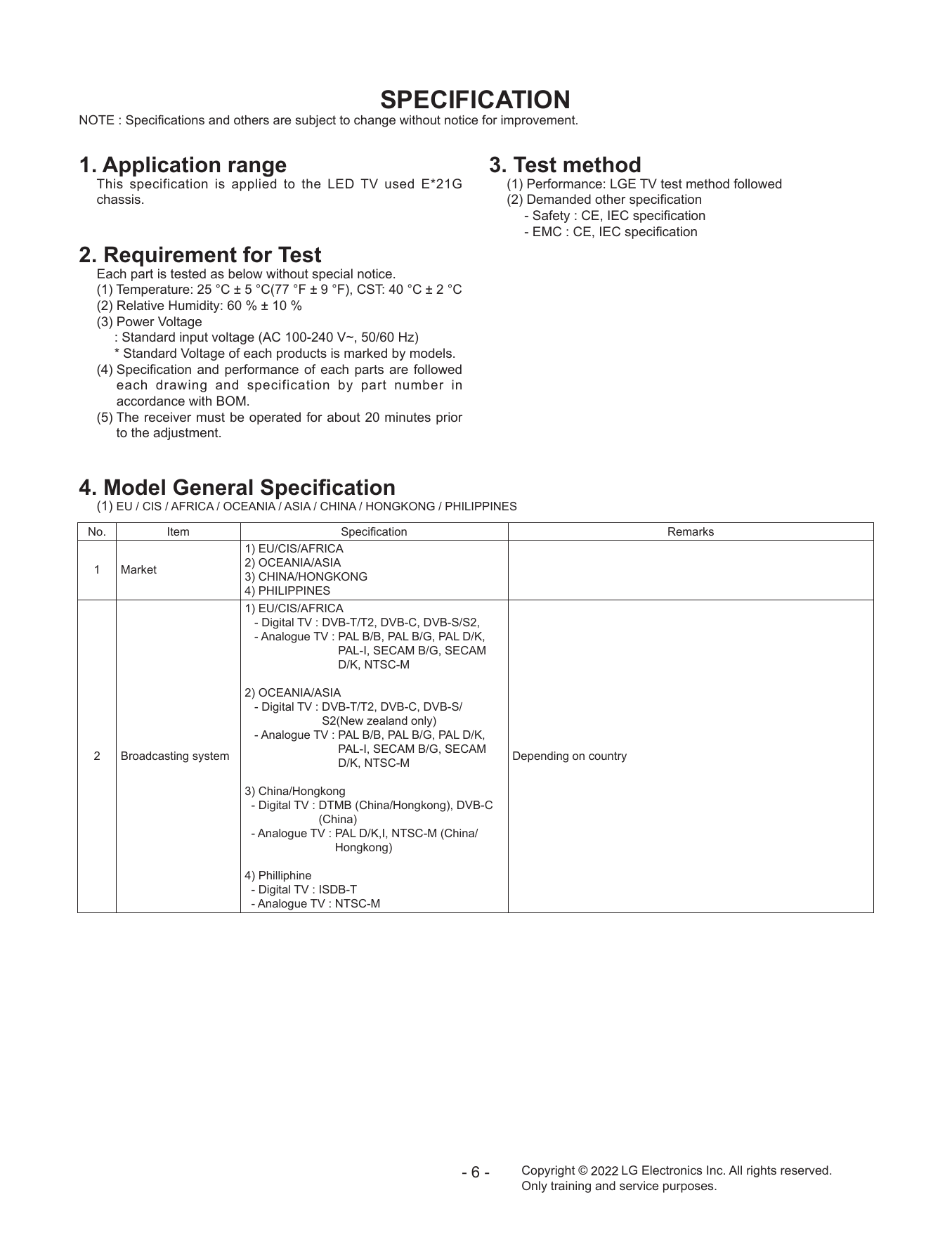
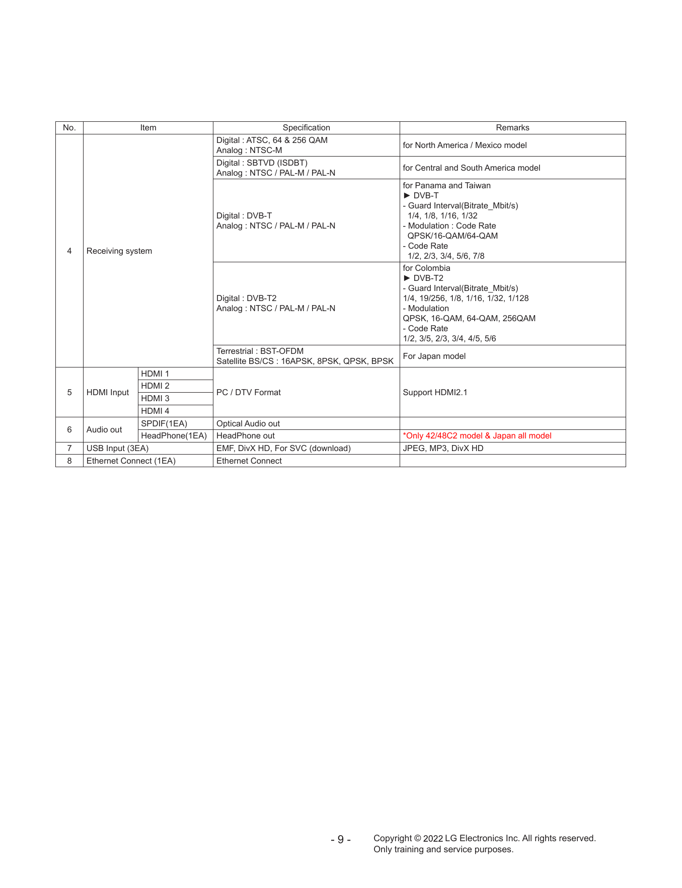
SPECIFICATION
СТРАНИЦА PDF
Страница 7
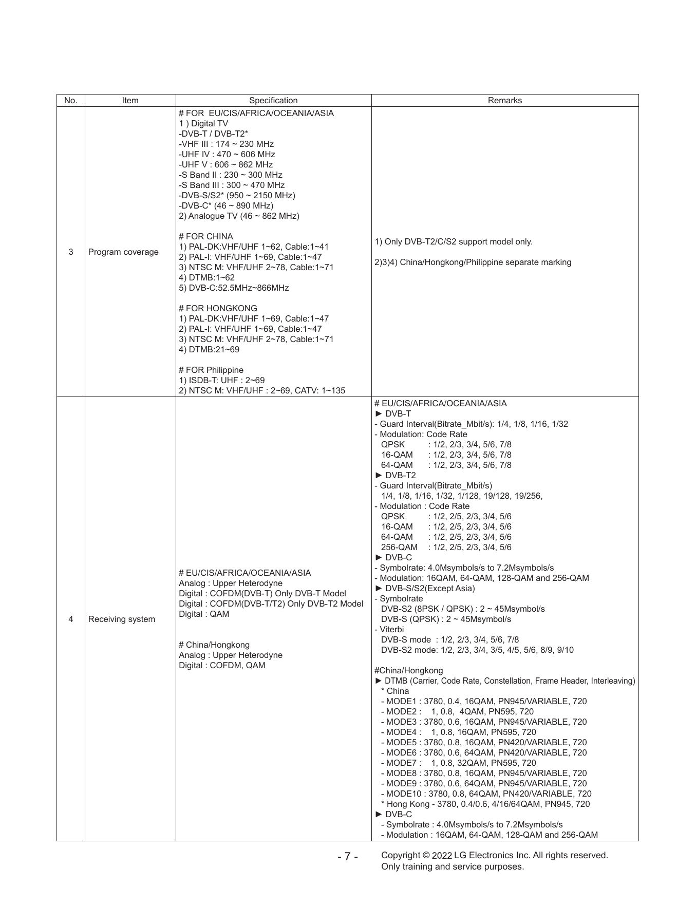
No. Item Specification Remarks
СТРАНИЦА PDF
Страница 8
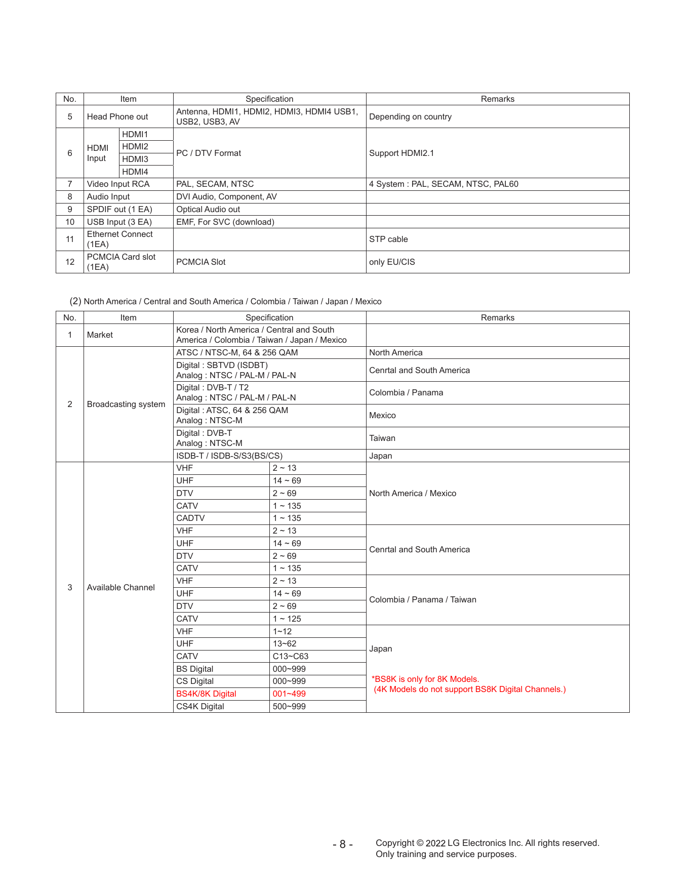
No. Item Specification Remarks
СТРАНИЦА PDF
Страница 9
No. Item Specification Remarks
СТРАНИЦА PDF
Страница 10
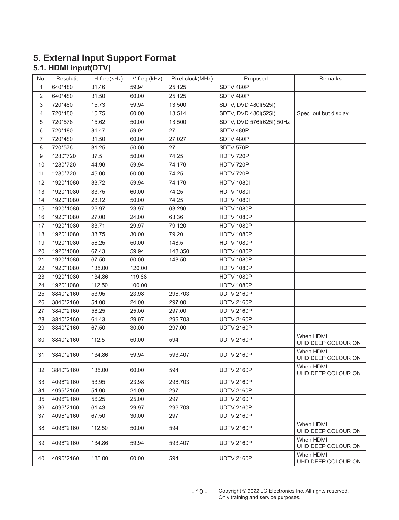
5. External Input Support Format
СТРАНИЦА PDF
Страница 11
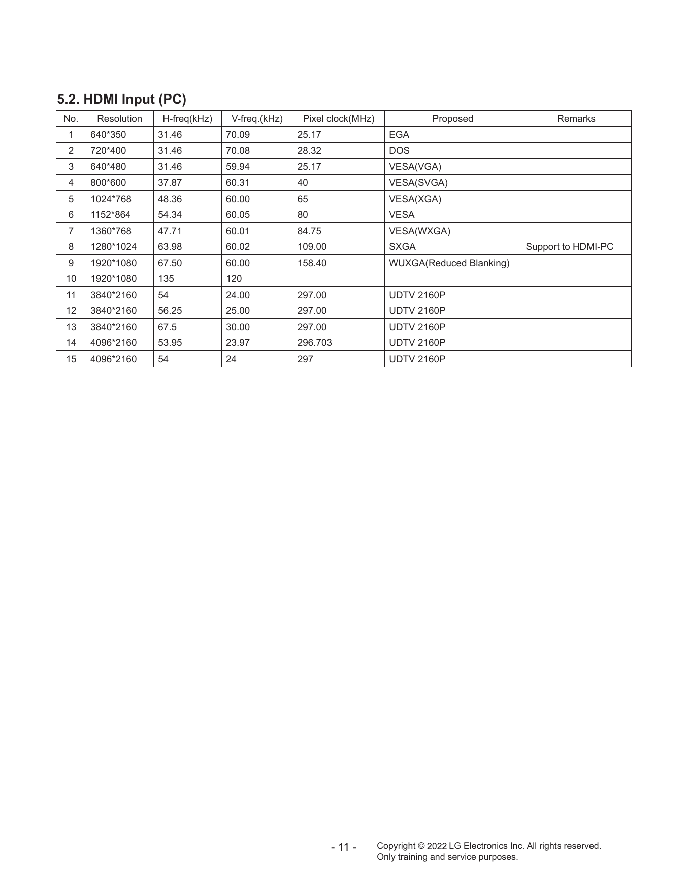
5.2. HDMI Input (PC)
СТРАНИЦА PDF
Страница 12
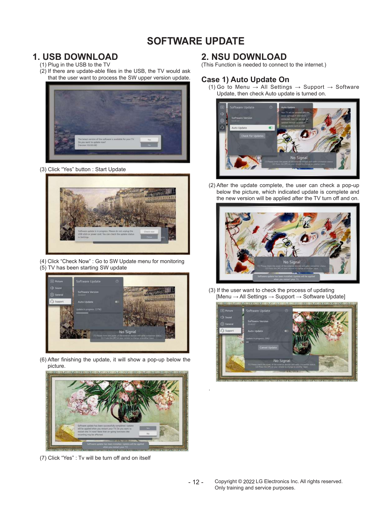
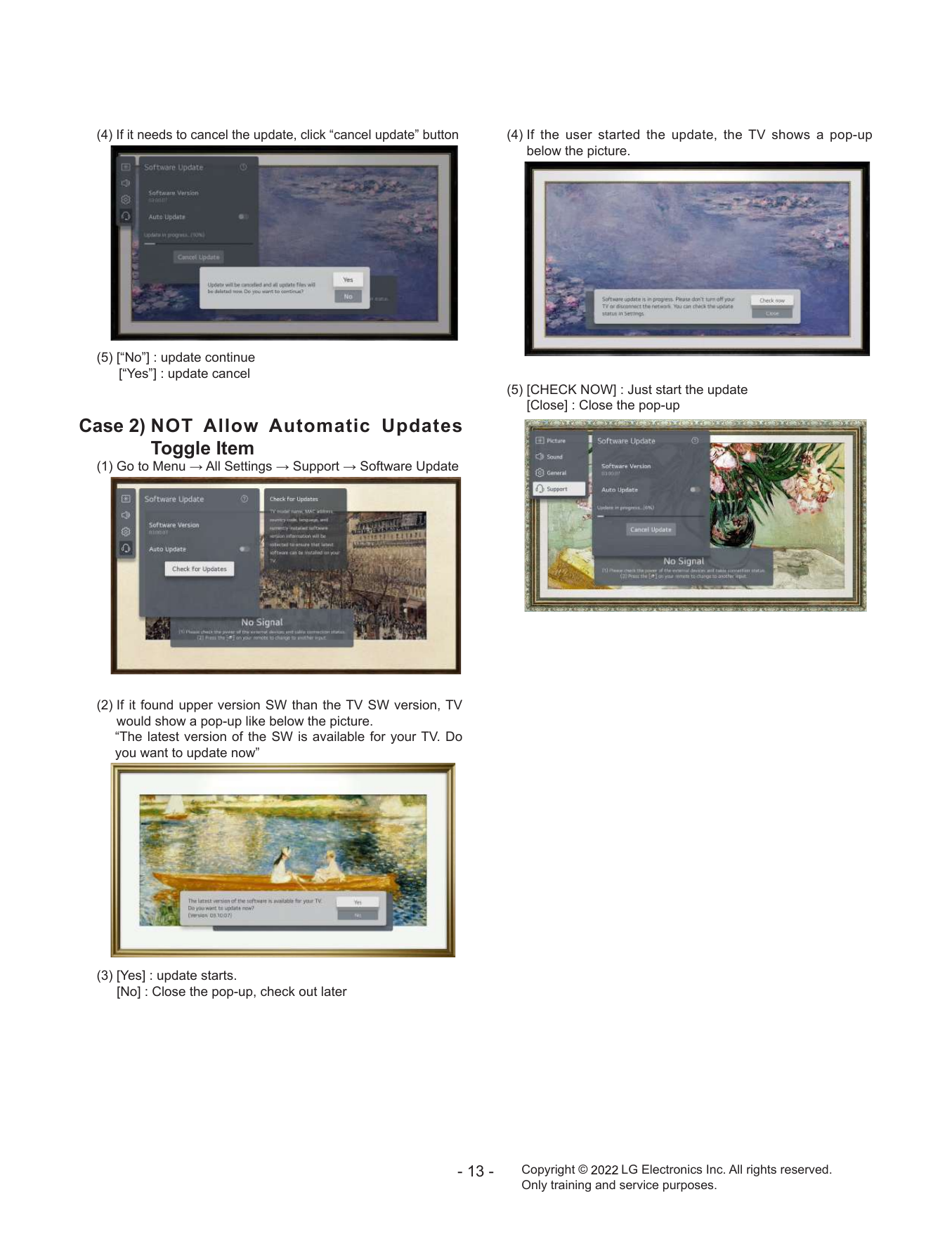
SOFTWARE UPDATE
Все сервис мануалы для телевизоров LG: http://webos-forums.ru/topic3291.html
OLED TV
SERVICE MANUAL
CHASSIS : E*21G
MODEL : OLED65G2**A
CAUTION
BEFORE SERVICING THE CHASSIS, READ THE SAFETY PRECAUTIONS IN THIS MANUAL.
P/NO : MFL71888124 (2201-REV00)
Any reproduction, duplication, distribution (including by way of email, facsimile or other electronic means),
publication, modification, copying or transmission of this Service Manual is STRICTLY PROHIBITED unless you
have obtained the prior written consent of the LG Electronics entity from which you received this Service Manual.
The material covered by this prohibition includes, without limitation, any text, graphics or logos in this Service
Manual.
Copyright © 2022 LG Electronics Inc. All rights reserved. Only training and service purposes.