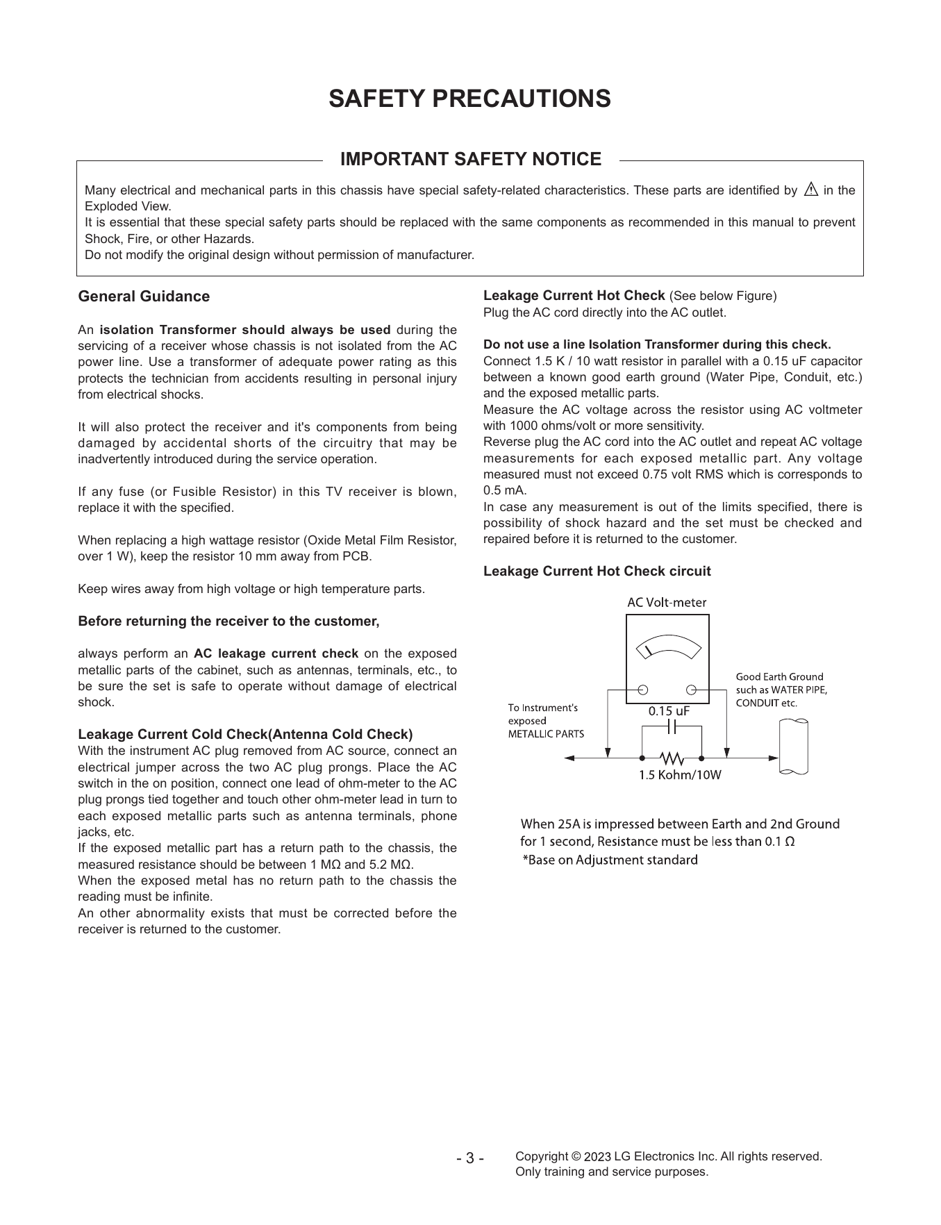
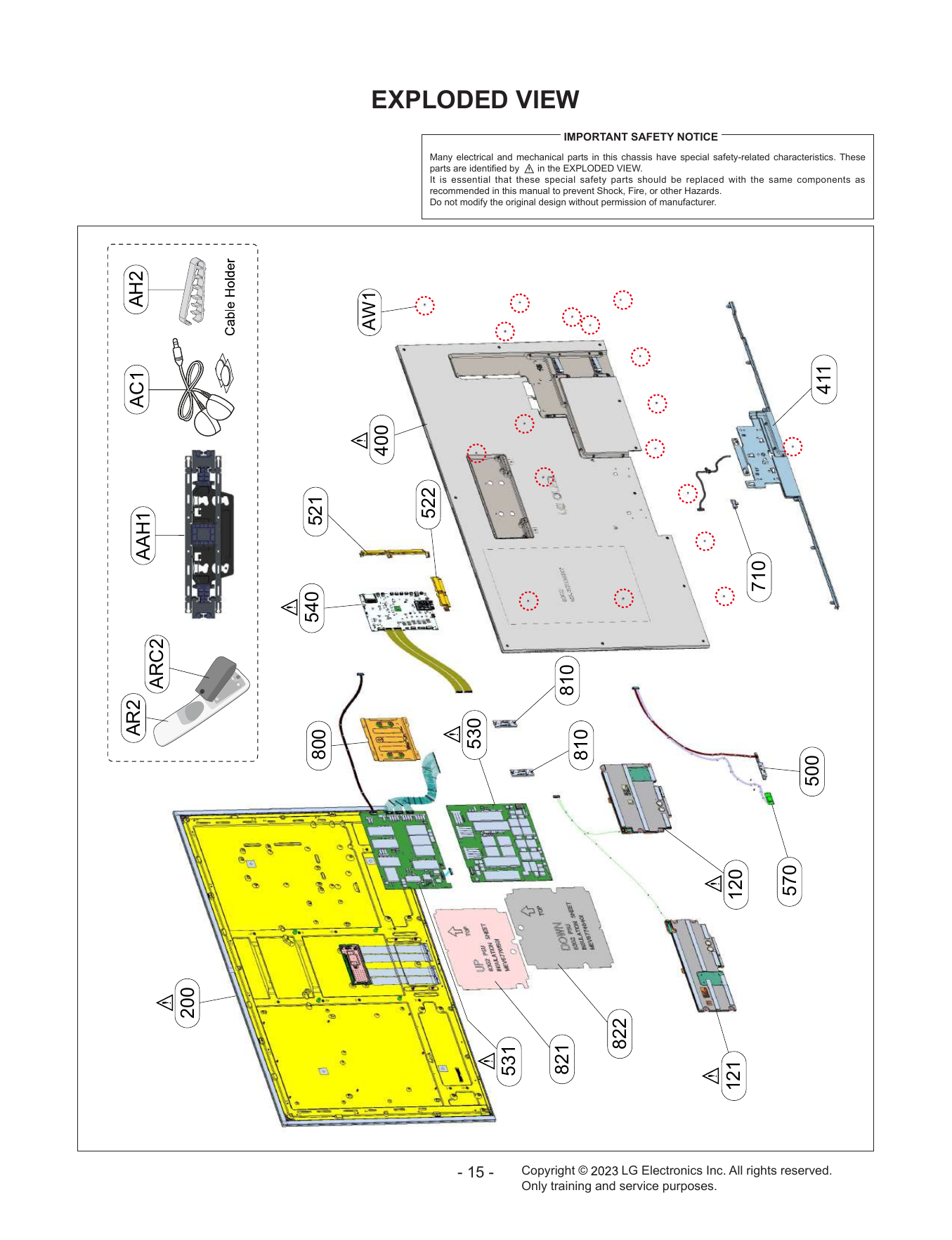
IMPORTANT SAFETY NOTICE
Many electrical and mechanical parts in this chassis have special safety-related characteristics. These parts are identified by in the
Exploded View.
It is ...
SERVICING PRECAUTIONS
CAUTION: Before servicing receivers covered by this service 2. After removing an electrical assembly equipped with ES
manual and its supplements and addenda, read and follow the devices, place ...
IC Remove/Replacement 3. Solder the connections.
Some chassis circuit boards have slotted holes (oblong) through CAUTION: Maintain original spacing between the replaced
which the IC l...
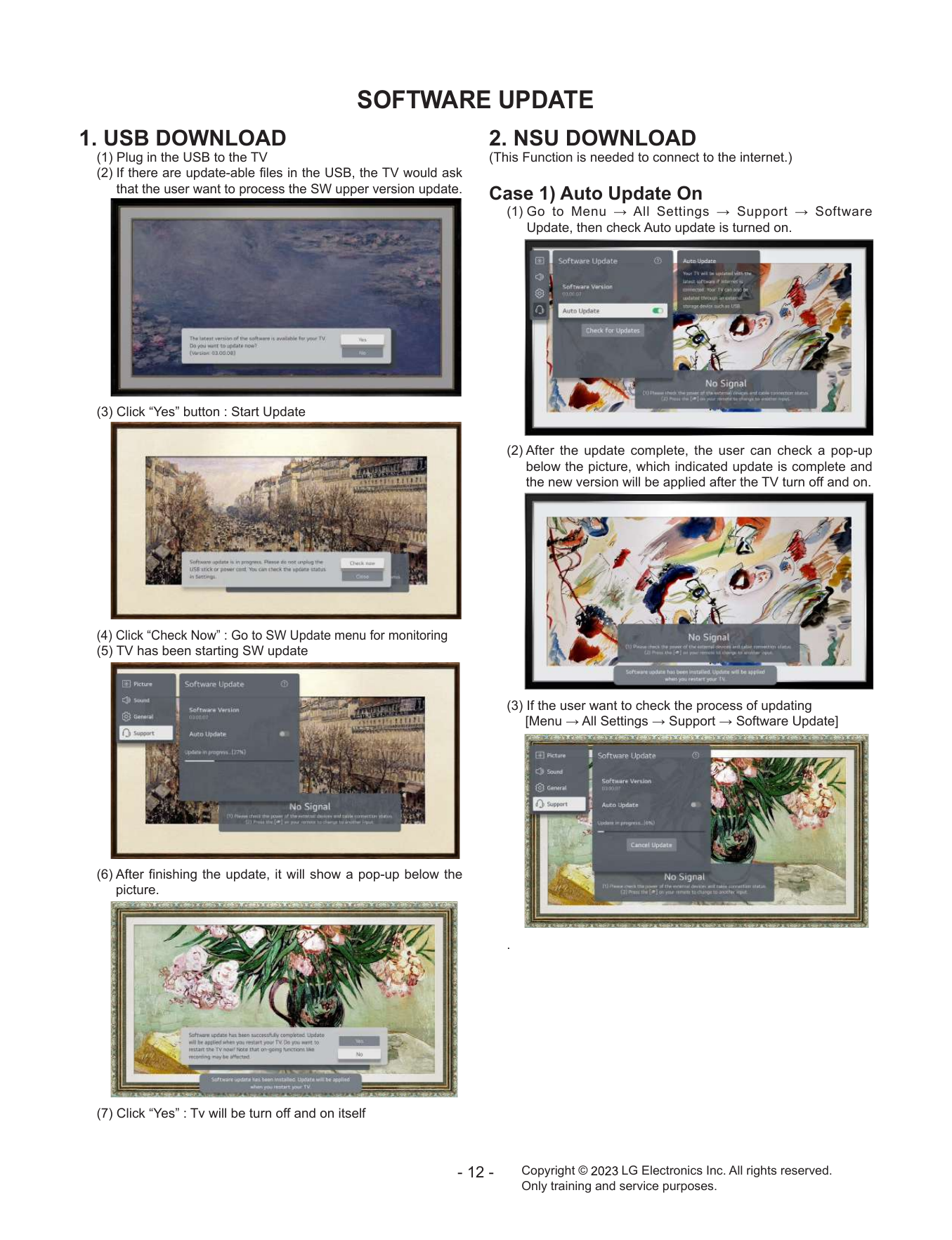
SOFTWARE UPDATE
1. USB DOWNLOAD 2. NSU DOWNLOAD
(1) Plug in the USB to the TV (This Function is needed to connect to the internet.)
(2) If there are update-a...