LG OLED48C3 Series
Сервис мануал для LG OLED48C3 Series
Размер файла: (11.58 mb)Производитель: LG
Просмотров: 283
- руководство по ремонту (сервис-мануал)
Сервис мануал для LG OLED48C3 Series
Размер файла: (11.58 mb)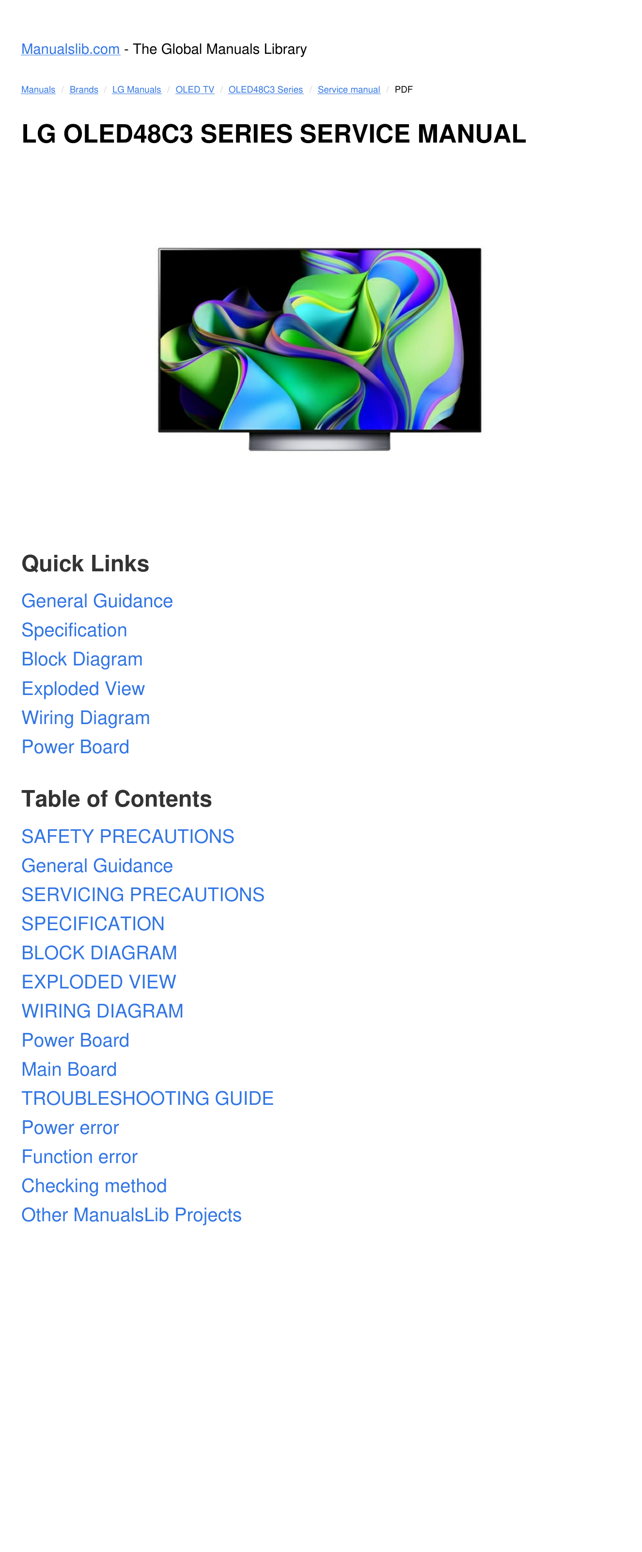

Руководство пользователя для LG OLED48C3RLA