Aspire one Series
Service Guide
Service guide files and updates are available
on the ACER/CSD web; for more information,
please refer to http://csd.acer.com.tw
PRINTED IN TAIWAN
Revision History
Please refer to the table below for the updates made on Aspire one Series service guide.
Date Chapter Updates
II
Copyright
Copyright © 2008 by Acer Incorporated. All rights reserved. No part of this publication may be reproduced,
transmitted, transcribed, stored in a retrieval system, or translated into any language or computer language, in
any form or by any means, electronic, mechanical, magnetic, optical, chemical, manual or otherwise, without
the prior written permission of Acer Incorporated.
Disclaimer
The information in this guide is subject to change without notice.
Acer Incorporated makes no representations or warranties, either expressed or implied, with respect to the
contents hereof and specifically disclaims any warranties of merchantability or fitness for any particular
purpose. Any Acer Incorporated software described in this manual is sold or licensed "as is". Should the
programs prove defective following their purchase, the buyer (and not Acer Incorporated, its distributor, or its
dealer) assumes the entire cost of all necessary servicing, repair, and any incidental or consequential
damages resulting from any defect in the software.
Acer is a registered trademark of Acer Corporation.
Intel is a registered trademark of Intel Corporation.
Pentium and Pentium II/III are trademarks of Intel Corporation.
Other brand and product names are trademarks and/or registered trademarks of their respective holders.
III
Conventions
The following conventions are used in this manual:
SCREEN MESSAGES Denotes actual messages that appear
on screen.
NOTE Gives bits and pieces of additional
information related to the current
topic.
WARNING Alerts you to any damage that might
result from doing or not doing specific
actions.
CAUTION Gives precautionary measures to
avoid possible hardware or software
problems.
IMPORTANT Reminds you to do specific actions
relevant to the accomplishment of
procedures.
IV
Preface
Before using this information and the product it supports, please read the following general information.
1. This Service Guide provides you with all technical information relating to the BASIC CONFIGURATION
decided for Acer's "global" product offering. To better fit local market requirements and enhance product
competitiveness, your regional office MAY have decided to extend the functionality of a machine (e.g.
add-on card, modem, or extra memory capability). These LOCALIZED FEATURES will NOT be covered
in this generic service guide. In such cases, please contact your regional offices or the responsible
personnel/channel to provide you with further technical details.
2. Please note WHEN ORDERING FRU PARTS, that you should check the most up-to-date information
available on your regional web or channel. If, for whatever reason, a part number change is made, it will
not be noted in the printed Service Guide. For ACER-AUTHORIZED SERVICE PROVIDERS, your Acer
office may have a DIFFERENT part number code to those given in the FRU list of this printed Service
Guide. You MUST use the list provided by your regional Acer office to order FRU parts for repair and
service of customer machines.
V
VI
Table of Contents
System Specifications 1
Features . . . . . . . . . . . . . . . . . . . . . . . . . . . . . . . . . . . . . . . . . . . . . . . . . . . . . . . . . . . .1
System Block Diagram . . . . . . . . . . . . . . . . . . . . . . . . . . . . . . . . . . . . . . . . . . . . . . . . .3
Your Acer Notebook tour . . . . . . . . . . . . . . . . . . . . . . . . . . . . . . . . . . . . . . . . . . . . . . .4
Front View . . . . . . . . . . . . . . . . . . . . . . . . . . . . . . . . . . . . . . . . . . . . . . . . . . . . . . .4
Closed Front View . . . . . . . . . . . . . . . . . . . . . . . . . . . . . . . . . . . . . . . . . . . . . . . . .5
Left View . . . . . . . . . . . . . . . . . . . . . . . . . . . . . . . . . . . . . . . . . . . . . . . . . . . . . . . .5
Right View . . . . . . . . . . . . . . . . . . . . . . . . . . . . . . . . . . . . . . . . . . . . . . . . . . . . . . .6
Rear View . . . . . . . . . . . . . . . . . . . . . . . . . . . . . . . . . . . . . . . . . . . . . . . . . . . . . . .6
Bottom View . . . . . . . . . . . . . . . . . . . . . . . . . . . . . . . . . . . . . . . . . . . . . . . . . . . . .7
Indicators . . . . . . . . . . . . . . . . . . . . . . . . . . . . . . . . . . . . . . . . . . . . . . . . . . . . . . .7
TouchPad Basics . . . . . . . . . . . . . . . . . . . . . . . . . . . . . . . . . . . . . . . . . . . . . . . . .8
Using the Keyboard . . . . . . . . . . . . . . . . . . . . . . . . . . . . . . . . . . . . . . . . . . . . . . . . . . .9
Lock Keys and embedded numeric keypad . . . . . . . . . . . . . . . . . . . . . . . . . . . . .9
Hot Keys . . . . . . . . . . . . . . . . . . . . . . . . . . . . . . . . . . . . . . . . . . . . . . . . . . . . . . .10
Special Key . . . . . . . . . . . . . . . . . . . . . . . . . . . . . . . . . . . . . . . . . . . . . . . . . . . . .11
Using the System Utilities . . . . . . . . . . . . . . . . . . . . . . . . . . . . . . . . . . . . . . . . . . . . . .12
Acer GridVista (dual-display compatible) . . . . . . . . . . . . . . . . . . . . . . . . . . . . . .12
Launch Manager . . . . . . . . . . . . . . . . . . . . . . . . . . . . . . . . . . . . . . . . . . . . . . . . .13
Hardware Specifications and Configurations . . . . . . . . . . . . . . . . . . . . . . . . . . . . . . .14
System Utilities 21
BIOS Setup Utility . . . . . . . . . . . . . . . . . . . . . . . . . . . . . . . . . . . . . . . . . . . . . . . . . . . .21
Navigating the BIOS Utility . . . . . . . . . . . . . . . . . . . . . . . . . . . . . . . . . . . . . . . . .21
Information . . . . . . . . . . . . . . . . . . . . . . . . . . . . . . . . . . . . . . . . . . . . . . . . . . . . .22
Main . . . . . . . . . . . . . . . . . . . . . . . . . . . . . . . . . . . . . . . . . . . . . . . . . . . . . . . . . .23
Security . . . . . . . . . . . . . . . . . . . . . . . . . . . . . . . . . . . . . . . . . . . . . . . . . . . . . . . .24
Boot . . . . . . . . . . . . . . . . . . . . . . . . . . . . . . . . . . . . . . . . . . . . . . . . . . . . . . . . . . .27
Exit . . . . . . . . . . . . . . . . . . . . . . . . . . . . . . . . . . . . . . . . . . . . . . . . . . . . . . . . . . .28
BIOS Flash Utility . . . . . . . . . . . . . . . . . . . . . . . . . . . . . . . . . . . . . . . . . . . . . . . . . . . .29
Remove HDD/BIOS Utility . . . . . . . . . . . . . . . . . . . . . . . . . . . . . . . . . . . . . . . . . . . . .31
Machine Disassembly and Replacement 35
Disassembly Requirements . . . . . . . . . . . . . . . . . . . . . . . . . . . . . . . . . . . . . . . . . . . .35
Related Information . . . . . . . . . . . . . . . . . . . . . . . . . . . . . . . . . . . . . . . . . . . . . . .35
General Information . . . . . . . . . . . . . . . . . . . . . . . . . . . . . . . . . . . . . . . . . . . . . . . . . .36
Pre-disassembly Instructions . . . . . . . . . . . . . . . . . . . . . . . . . . . . . . . . . . . . . . .36
Disassembly Process . . . . . . . . . . . . . . . . . . . . . . . . . . . . . . . . . . . . . . . . . . . . .36
External Module Disassembly Process . . . . . . . . . . . . . . . . . . . . . . . . . . . . . . . . . . .37
External Modules Disassembly Flowchart . . . . . . . . . . . . . . . . . . . . . . . . . . . . .37
Removing the Battery Pack . . . . . . . . . . . . . . . . . . . . . . . . . . . . . . . . . . . . . . . .38
Removing the 3G Cover . . . . . . . . . . . . . . . . . . . . . . . . . . . . . . . . . . . . . . . . . . .38
Removing the Keyboard . . . . . . . . . . . . . . . . . . . . . . . . . . . . . . . . . . . . . . . . . . .39
Removing the Upper and Lower Covers . . . . . . . . . . . . . . . . . . . . . . . . . . . . . . .40
LCD Module Disassembly Process . . . . . . . . . . . . . . . . . . . . . . . . . . . . . . . . . . . . . .43
LCD Module Disassembly Flowchart . . . . . . . . . . . . . . . . . . . . . . . . . . . . . . . . .43
Removing the LCD Module . . . . . . . . . . . . . . . . . . . . . . . . . . . . . . . . . . . . . . . . .44
Removing the LCD Bezel . . . . . . . . . . . . . . . . . . . . . . . . . . . . . . . . . . . . . . . . . .45
Removing the Camera Board . . . . . . . . . . . . . . . . . . . . . . . . . . . . . . . . . . . . . . .46
Removing the MIC Board . . . . . . . . . . . . . . . . . . . . . . . . . . . . . . . . . . . . . . . . . .47
Removing the LCD Panel . . . . . . . . . . . . . . . . . . . . . . . . . . . . . . . . . . . . . . . . . .48
Removing the LCD Brackets and FPC Cable . . . . . . . . . . . . . . . . . . . . . . . . . . .49
Main Unit Disassembly Process . . . . . . . . . . . . . . . . . . . . . . . . . . . . . . . . . . . . . . . . .51
Main Unit Disassembly Flowchart . . . . . . . . . . . . . . . . . . . . . . . . . . . . . . . . . . . .51
VII
Table of Contents
Removing the WLAN Module . . . . . . . . . . . . . . . . . . . . . . . . . . . . . . . . . . . . . . .52
Removing the USB/LED/Power/Card Reader Board . . . . . . . . . . . . . . . . . . . . .53
Removing the SSD Module . . . . . . . . . . . . . . . . . . . . . . . . . . . . . . . . . . . . . . . . .54
Removing the Mainboard . . . . . . . . . . . . . . . . . . . . . . . . . . . . . . . . . . . . . . . . . .56
Removing the Speaker Module . . . . . . . . . . . . . . . . . . . . . . . . . . . . . . . . . . . . . .57
Removing the Hard Disk Drive Module . . . . . . . . . . . . . . . . . . . . . . . . . . . . . . . .58
Removing the DIMM Module . . . . . . . . . . . . . . . . . . . . . . . . . . . . . . . . . . . . . . .60
Removing the Thermal Module . . . . . . . . . . . . . . . . . . . . . . . . . . . . . . . . . . . . . .61
LCD Module Reassembly Procedure . . . . . . . . . . . . . . . . . . . . . . . . . . . . . . . . . . . . .63
Replacing the LCD Brackets and FPC Cable . . . . . . . . . . . . . . . . . . . . . . . . . . .63
Replacing the LCD Panel . . . . . . . . . . . . . . . . . . . . . . . . . . . . . . . . . . . . . . . . . .64
Replacing the Mic Board . . . . . . . . . . . . . . . . . . . . . . . . . . . . . . . . . . . . . . . . . . .65
Replacing the Camera Board . . . . . . . . . . . . . . . . . . . . . . . . . . . . . . . . . . . . . . .65
Replacing the LCD Bezel . . . . . . . . . . . . . . . . . . . . . . . . . . . . . . . . . . . . . . . . . .66
Main Module Reassembly Procedure . . . . . . . . . . . . . . . . . . . . . . . . . . . . . . . . . . . . .67
Replacing the Thermal Module . . . . . . . . . . . . . . . . . . . . . . . . . . . . . . . . . . . . . .67
Replacing the DIMM Module . . . . . . . . . . . . . . . . . . . . . . . . . . . . . . . . . . . . . . . .67
Replacing the Hard Disk Drive Module . . . . . . . . . . . . . . . . . . . . . . . . . . . . . . . .68
Replacing the Speaker Module . . . . . . . . . . . . . . . . . . . . . . . . . . . . . . . . . . . . . .68
Replacing the Mainboard . . . . . . . . . . . . . . . . . . . . . . . . . . . . . . . . . . . . . . . . . .70
Replacing the SDD Module . . . . . . . . . . . . . . . . . . . . . . . . . . . . . . . . . . . . . . . . .71
Replacing the USB/LED/Power/Card Reader Board . . . . . . . . . . . . . . . . . . . . .72
Replacing the WLAN Board . . . . . . . . . . . . . . . . . . . . . . . . . . . . . . . . . . . . . . . .73
Replacing the LCM Module . . . . . . . . . . . . . . . . . . . . . . . . . . . . . . . . . . . . . . . . .73
Replacing the Upper Cover . . . . . . . . . . . . . . . . . . . . . . . . . . . . . . . . . . . . . . . . .75
Replacing the Keyboard . . . . . . . . . . . . . . . . . . . . . . . . . . . . . . . . . . . . . . . . . . .76
Replacing the 3G cover . . . . . . . . . . . . . . . . . . . . . . . . . . . . . . . . . . . . . . . . . . .77
Replacing the Battery . . . . . . . . . . . . . . . . . . . . . . . . . . . . . . . . . . . . . . . . . . . . .77
Troubleshooting 79
Common Problems . . . . . . . . . . . . . . . . . . . . . . . . . . . . . . . . . . . . . . . . . . . . . . . . . . .79
Power On Issue . . . . . . . . . . . . . . . . . . . . . . . . . . . . . . . . . . . . . . . . . . . . . . . . .80
No Display Issue . . . . . . . . . . . . . . . . . . . . . . . . . . . . . . . . . . . . . . . . . . . . . . . . .81
Random Loss of BIOS Settings . . . . . . . . . . . . . . . . . . . . . . . . . . . . . . . . . . . . .83
LCD Failure . . . . . . . . . . . . . . . . . . . . . . . . . . . . . . . . . . . . . . . . . . . . . . . . . . . . .84
Built-In Keyboard Failure . . . . . . . . . . . . . . . . . . . . . . . . . . . . . . . . . . . . . . . . . .84
TouchPad Failure . . . . . . . . . . . . . . . . . . . . . . . . . . . . . . . . . . . . . . . . . . . . . . . .85
Internal Speaker Failure . . . . . . . . . . . . . . . . . . . . . . . . . . . . . . . . . . . . . . . . . . .85
Internal Microphone Failure . . . . . . . . . . . . . . . . . . . . . . . . . . . . . . . . . . . . . . . .87
HDD Not Operating Correctly . . . . . . . . . . . . . . . . . . . . . . . . . . . . . . . . . . . . . . .88
USB Failure (Rightside) . . . . . . . . . . . . . . . . . . . . . . . . . . . . . . . . . . . . . . . . . . .89
Power Button Failure . . . . . . . . . . . . . . . . . . . . . . . . . . . . . . . . . . . . . . . . . . . . .89
External Mouse Failure . . . . . . . . . . . . . . . . . . . . . . . . . . . . . . . . . . . . . . . . . . . .90
Other Failures . . . . . . . . . . . . . . . . . . . . . . . . . . . . . . . . . . . . . . . . . . . . . . . . . . .90
Intermittent Problems . . . . . . . . . . . . . . . . . . . . . . . . . . . . . . . . . . . . . . . . . . . . . . . . .91
Undetermined Problems . . . . . . . . . . . . . . . . . . . . . . . . . . . . . . . . . . . . . . . . . . . . . . .91
Frequently Asked Questions (FAQ) . . . . . . . . . . . . . . . . . . . . . . . . . . . . . . . . . . . . . .92
POST Code Reference Tables . . . . . . . . . . . . . . . . . . . . . . . . . . . . . . . . . . . . . . . . .105
Sec: . . . . . . . . . . . . . . . . . . . . . . . . . . . . . . . . . . . . . . . . . . . . . . . . . . . . . . . . . .105
Memory: . . . . . . . . . . . . . . . . . . . . . . . . . . . . . . . . . . . . . . . . . . . . . . . . . . . . . .105
BDS & Specific action: . . . . . . . . . . . . . . . . . . . . . . . . . . . . . . . . . . . . . . . . . . .106
Each PEIM entry point used in 80_PORT . . . . . . . . . . . . . . . . . . . . . . . . . . . . .108
Each Driver entry point used in 80_PORT . . . . . . . . . . . . . . . . . . . . . . . . . . . .108
Each SmmDriver entry point used in 80_PORT . . . . . . . . . . . . . . . . . . . . . . . .111
VIII
Table of Contents
Jumper and Connector Locations 113
Top View . . . . . . . . . . . . . . . . . . . . . . . . . . . . . . . . . . . . . . . . . . . . . . . . . . . . . . . . . .113
Bottom View . . . . . . . . . . . . . . . . . . . . . . . . . . . . . . . . . . . . . . . . . . . . . . . . . . . . . . .114
Clearing Password Check and BIOS Recovery . . . . . . . . . . . . . . . . . . . . . . . . . . . .115
Clearing Password Check . . . . . . . . . . . . . . . . . . . . . . . . . . . . . . . . . . . . . . . . .115
BIOS Recovery by Crisis Disk . . . . . . . . . . . . . . . . . . . . . . . . . . . . . . . . . . . . .116
FRU (Field Replaceable Unit) List 117
Aspire 7730/7730G Exploded Diagrams . . . . . . . . . . . . . . . . . . . . . . . . . . . . . . . . .118
Upper Cover . . . . . . . . . . . . . . . . . . . . . . . . . . . . . . . . . . . . . . . . . . . . . . . . . . .118
Lower Cover . . . . . . . . . . . . . . . . . . . . . . . . . . . . . . . . . . . . . . . . . . . . . . . . . . .119
LCD Panel . . . . . . . . . . . . . . . . . . . . . . . . . . . . . . . . . . . . . . . . . . . . . . . . . . . . .120
Model Definition and Configuration 128
Aspire one Series . . . . . . . . . . . . . . . . . . . . . . . . . . . . . . . . . . . . . . . . . . . . . . . . . . .128
Test Compatible Components 151
Microsoft® Windows® Vista Environment Test . . . . . . . . . . . . . . . . . . . . . . . . . . . .152
PCMCIA LAN Card Test . . . . . . . . . . . . . . . . . . . . . . . . . . . . . . . . . . . . . . . . . .152
Express Card Test . . . . . . . . . . . . . . . . . . . . . . . . . . . . . . . . . . . . . . . . . . . . . .152
Display Port Test . . . . . . . . . . . . . . . . . . . . . . . . . . . . . . . . . . . . . . . . . . . . . . . .152
USB Port Test . . . . . . . . . . . . . . . . . . . . . . . . . . . . . . . . . . . . . . . . . . . . . . . . . .152
Access Point Test . . . . . . . . . . . . . . . . . . . . . . . . . . . . . . . . . . . . . . . . . . . . . . .153
Bluetooth Test . . . . . . . . . . . . . . . . . . . . . . . . . . . . . . . . . . . . . . . . . . . . . . . . . .153
Card Reader Test . . . . . . . . . . . . . . . . . . . . . . . . . . . . . . . . . . . . . . . . . . . . . . .154
Audio Jacks Port Test . . . . . . . . . . . . . . . . . . . . . . . . . . . . . . . . . . . . . . . . . . . .154
Port Replicator Test . . . . . . . . . . . . . . . . . . . . . . . . . . . . . . . . . . . . . . . . . . . . .154
Online Support Information 155
Index 157
IX
Table of Contents
X
Chapter 1
System Specifications
Features
Below is a brief summary of the computer’s many feature:
Operating System
• Microsoft Windows® XP™ / Linux
Platform
• Diamondville Atrom series standard voltage 533FSB processors
• Intel 945GMS + ICH7M Chipset
System Memory
• One DDRII SO-DIMM slots support 512MB to 1024MB system memory
• 512MB on board memory
• 1MB Flash BIOS
Display and graphics
• 8.9” Wide Screen LCD (1024x600)
• LED backlight LCD
Storage subsystem
• 8GB SSD module PATA interface
• Fixed type for 80GB or higher capacity SATA HDD
Audio
• HD audio codec
• Internal Digital MIC
Dimensions and Weight
• 248 (W) x 169.4 (D) x 29.5 (H) mm (ME dimension)
• 995g weight with 8.9” LCD and 8GB SSD
Communication
• On-Board PCI-E 10/100 LAN
• Mini-card Wireless LAN
• Wake-on-LAN support
• 3G module through USB
Chapter 1 1
Privacy control
• BIOS user, supervisor, and power on passwords
• Kensington lock slot
Power subsystem
• 2-cell 2200mAh
• 6-cell 5200mAh
• 30W 19V 3-pin AC adapter
Special keys and controls
• New Acer Aspire one keyboard support
• Power button and Wireless LAN/3G switch
I/O interface
• 2 * Express card slot
• 1 * VGA port, 15 pins
• 1 * Microphone-in/Line-in
• 1 * Line-out / Headphone out
• 3 * External USB 2.0
• 1 * DC in jack
• 1 * RJ-45 jack for LAN
• 1 * Internal Digital MIC
• 1 * 5-in-1 card reader
• 1 * SD card reader
Environment
• Temperature:
• Operating: 5 °C to 35 °C
• Non-operating: -20 °C to 65 °C
• Humidity (non-condensing):
• Operating: 20% to 80%
• Non-operating: 20% to 80%
2 Chapter 1
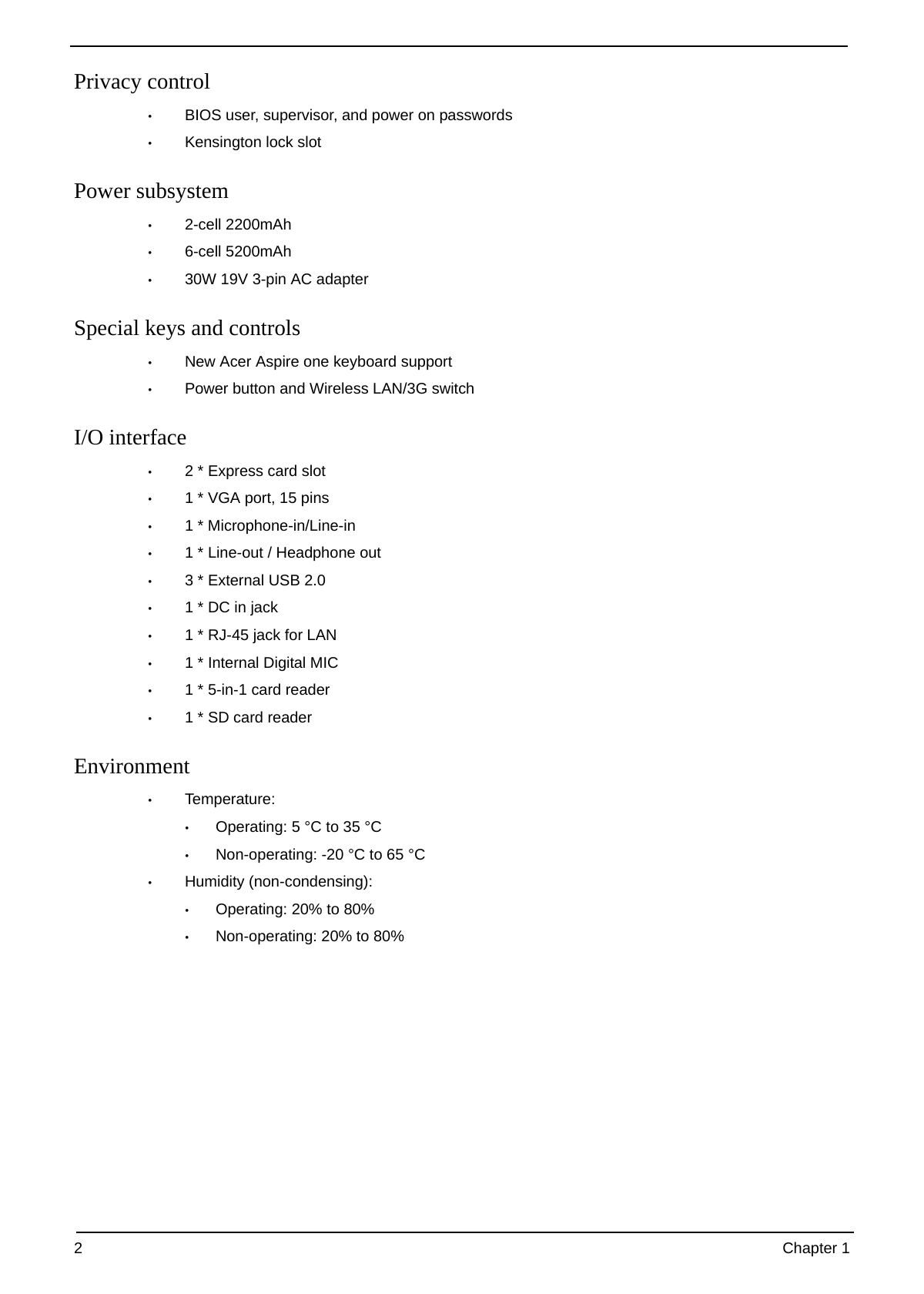
System Block Diagram
Chapter 1 3
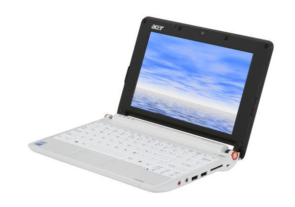
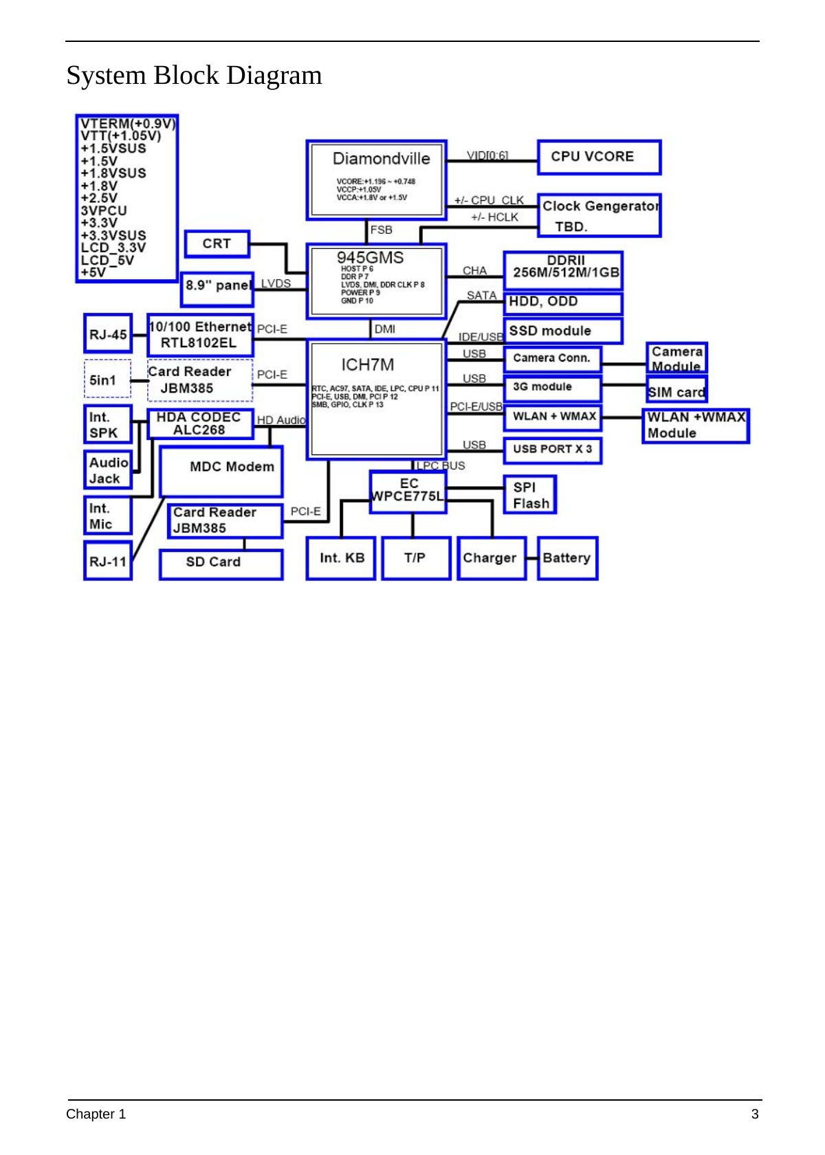
Your Acer Notebook tour
After knowing your computer features, let us show you around your new computer.
Front View
No. Icon Item Description
1 Acer Crystal Eye Web camera for video communication (only for
Webcam certain models).
2 Microphone Internal microphone for sound recording.
3 Display screen Also called Liquid-Crystal Display (LCD), displays
computer output.
4 Status indicators Light-Emitting Diodes (LEDs) that light up to show
the status of the computer's functions and
components.
5 Keyboard For entering data into your computer.
6 TouchPad Touch-sensitive pointing device which functions like
a computer mouse.
7 Click buttons (left The left and right buttons function like the left and
and right) right mouse buttons.
8 Wireless LAN Indicates the status of wireless LAN
communication communication.
indicator
9 Power button Turns the computer on and off.
4 Chapter 1
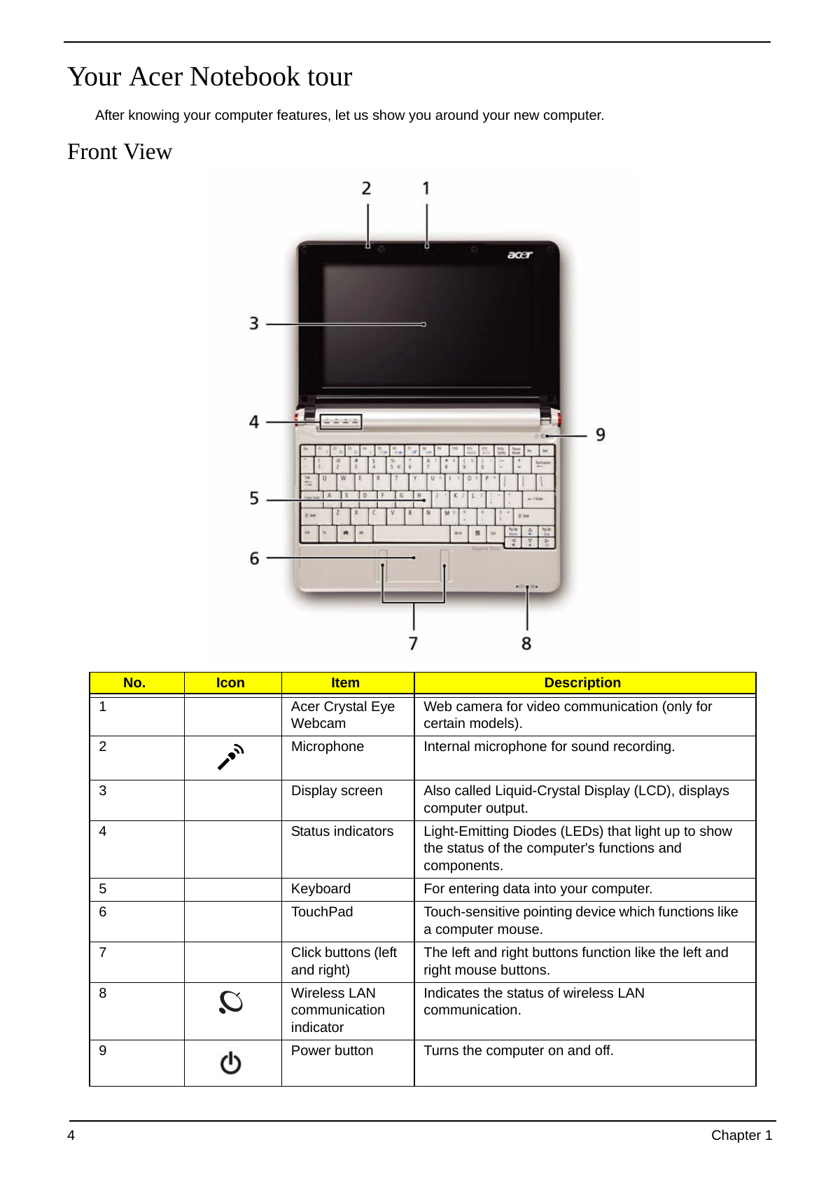
Closed Front View
No. Icon Item Description
1 Wireless Enables/disables the wireless function.
communication
switch
Left View
No. Icon Item Description
1 DC-in jack Connects to an AC adapter
2 External display Connects to a display device
(VGA) port (e.g. external monitor, LCD projector).
3 Ventilation slots Enable the computer to stay cool, even after
and cooling fan prolonged use.
Note: Do not cover or obstruct the fan opening.
4 Ethernet (RJ-45) Connects to an Ethernet 10/100-based
port network.
5 USB 2.0 port Connect to USB 2.0 devices (e.g. USB mouse).
6 Storage Accepts one Secure Digital (SD) card, used to
expansion slot expand the capacity of My Files. Push the card
inwards and let it pop out before removing.
Note: This slot is for expanding My Files long-
term. For transferring files to and from other
devices, use the 5-in-1 card reader.
Chapter 1 5
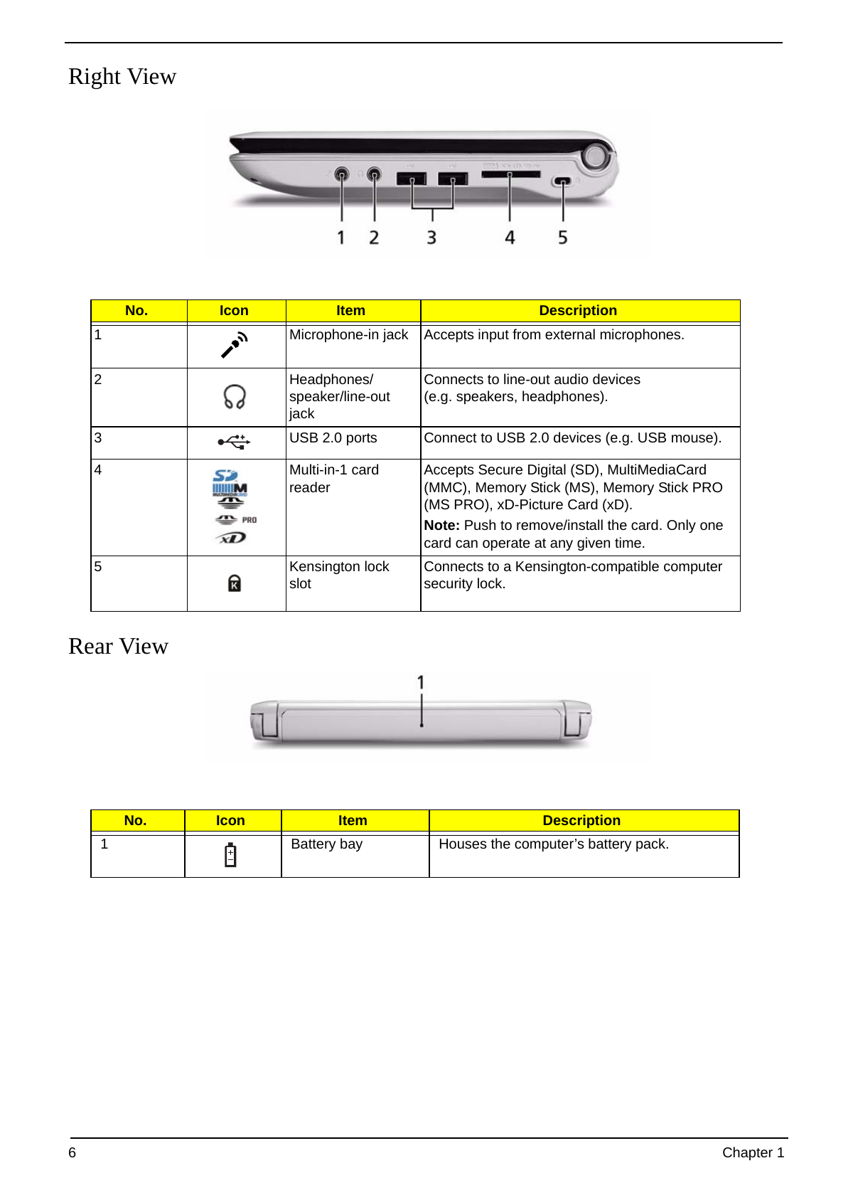
Right View
No. Icon Item Description
1 Microphone-in jack Accepts input from external microphones.
2 Headphones/ Connects to line-out audio devices
speaker/line-out (e.g. speakers, headphones).
jack
3 USB 2.0 ports Connect to USB 2.0 devices (e.g. USB mouse).
4 Multi-in-1 card Accepts Secure Digital (SD), MultiMediaCard
reader (MMC), Memory Stick (MS), Memory Stick PRO
(MS PRO), xD-Picture Card (xD).
Note: Push to remove/install the card. Only one
card can operate at any given time.
5 Kensington lock Connects to a Kensington-compatible computer
slot security lock.
Rear View
No. Icon Item Description
1 Battery bay Houses the computer’s battery pack.
6 Chapter 1
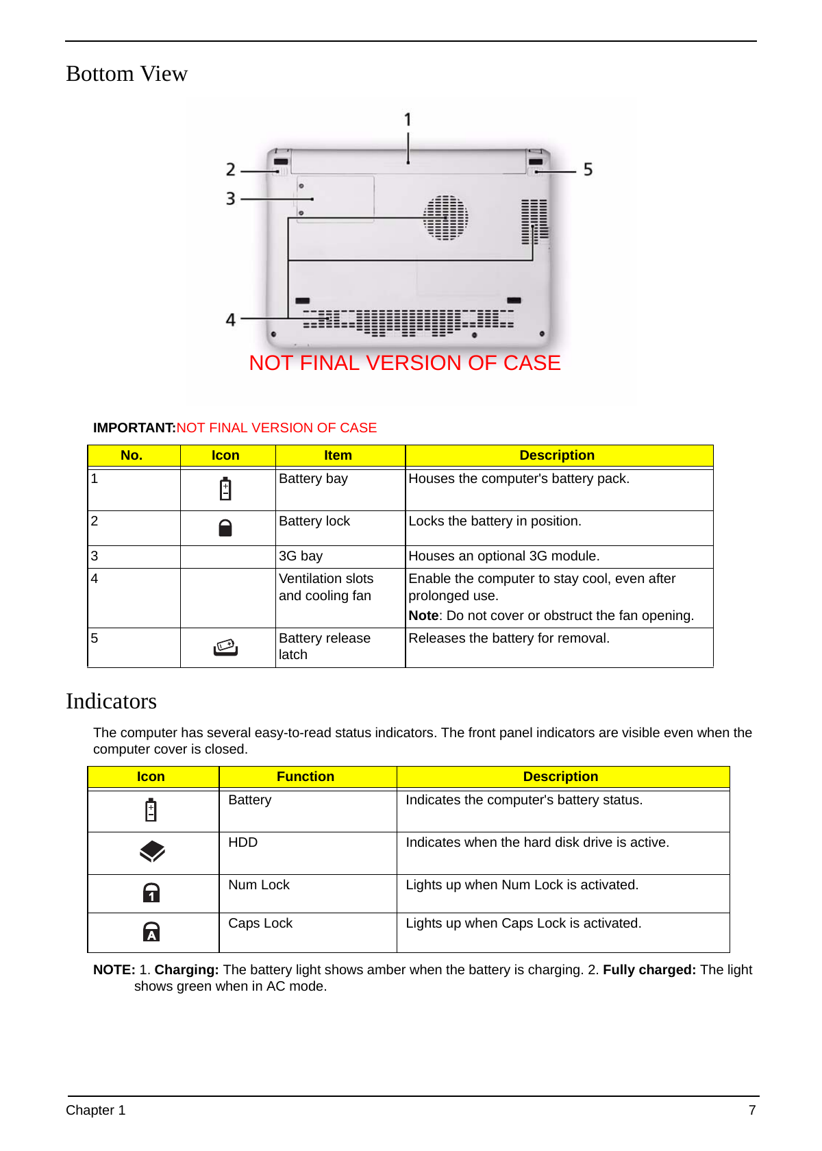
Bottom View
NOT FINAL VERSION OF CASE
IMPORTANT:NOT FINAL VERSION OF CASE
No. Icon Item Description
1 Battery bay Houses the computer's battery pack.
2 Battery lock Locks the battery in position.
3 3G bay Houses an optional 3G module.
4 Ventilation slots Enable the computer to stay cool, even after
and cooling fan prolonged use.
Note: Do not cover or obstruct the fan opening.
5 Battery release Releases the battery for removal.
latch
Indicators
The computer has several easy-to-read status indicators. The front panel indicators are visible even when the
computer cover is closed.
Icon Function Description
Battery Indicates the computer's battery status.
HDD Indicates when the hard disk drive is active.
Num Lock Lights up when Num Lock is activated.
Caps Lock Lights up when Caps Lock is activated.
NOTE: 1. Charging: The battery light shows amber when the battery is charging. 2. Fully charged: The light
shows green when in AC mode.
Chapter 1 7
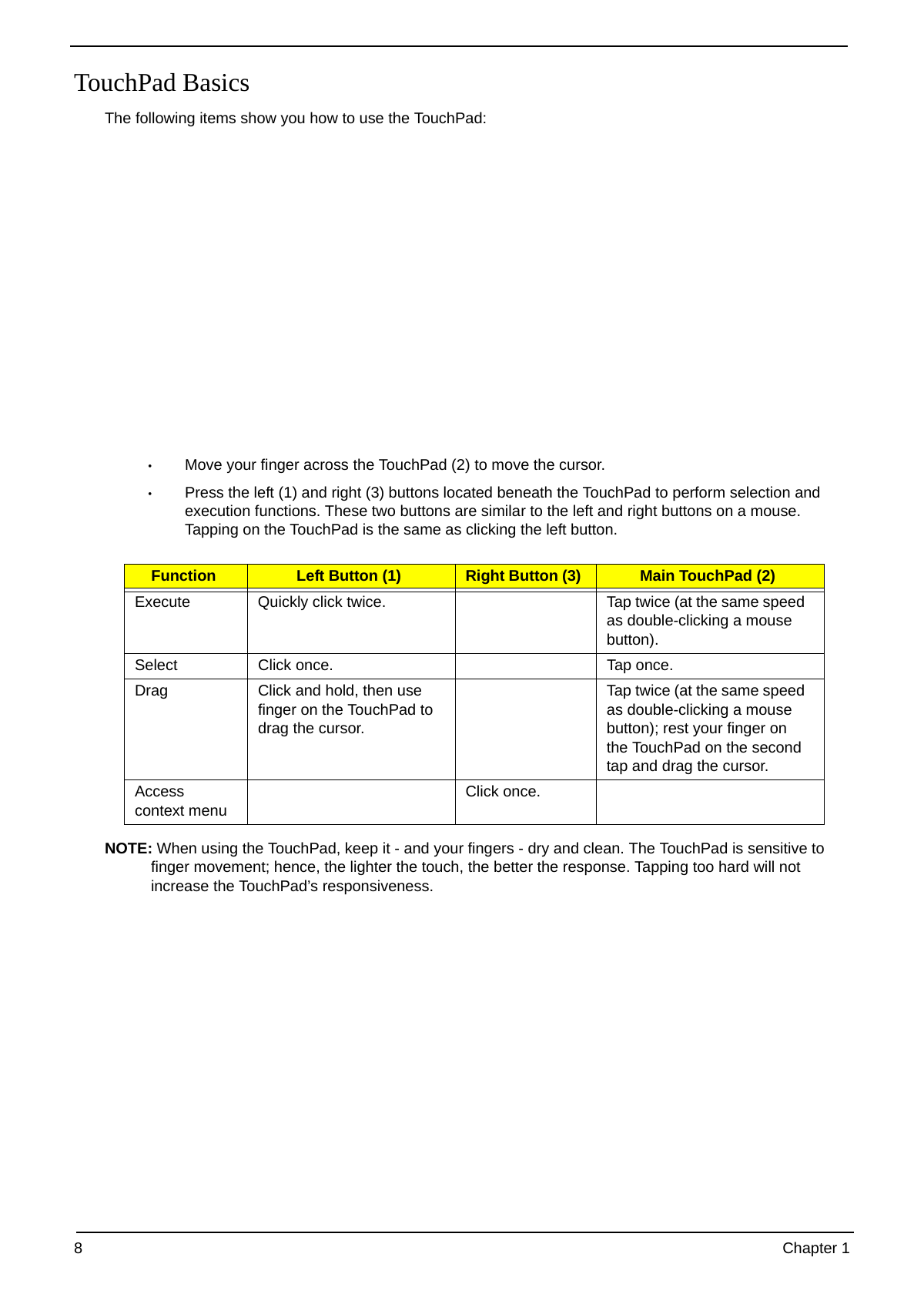
TouchPad Basics
The following items show you how to use the TouchPad:
• Move your finger across the TouchPad (2) to move the cursor.
• Press the left (1) and right (3) buttons located beneath the TouchPad to perform selection and
execution functions. These two buttons are similar to the left and right buttons on a mouse.
Tapping on the TouchPad is the same as clicking the left button.
Function Left Button (1) Right Button (3) Main TouchPad (2)
Execute Quickly click twice. Tap twice (at the same speed
as double-clicking a mouse
button).
Select Click once. Tap once.
Drag Click and hold, then use Tap twice (at the same speed
finger on the TouchPad to as double-clicking a mouse
drag the cursor. button); rest your finger on
the TouchPad on the second
tap and drag the cursor.
Access Click once.
context menu
NOTE: When using the TouchPad, keep it - and your fingers - dry and clean. The TouchPad is sensitive to
finger movement; hence, the lighter the touch, the better the response. Tapping too hard will not
increase the TouchPad’s responsiveness.
8 Chapter 1
Using the Keyboard
Your Aspire one has a close-to-full-sized keyboard and an embedded numeric keypad, separate cursor, lock,
function and special keys.
Lock Keys and embedded numeric keypad
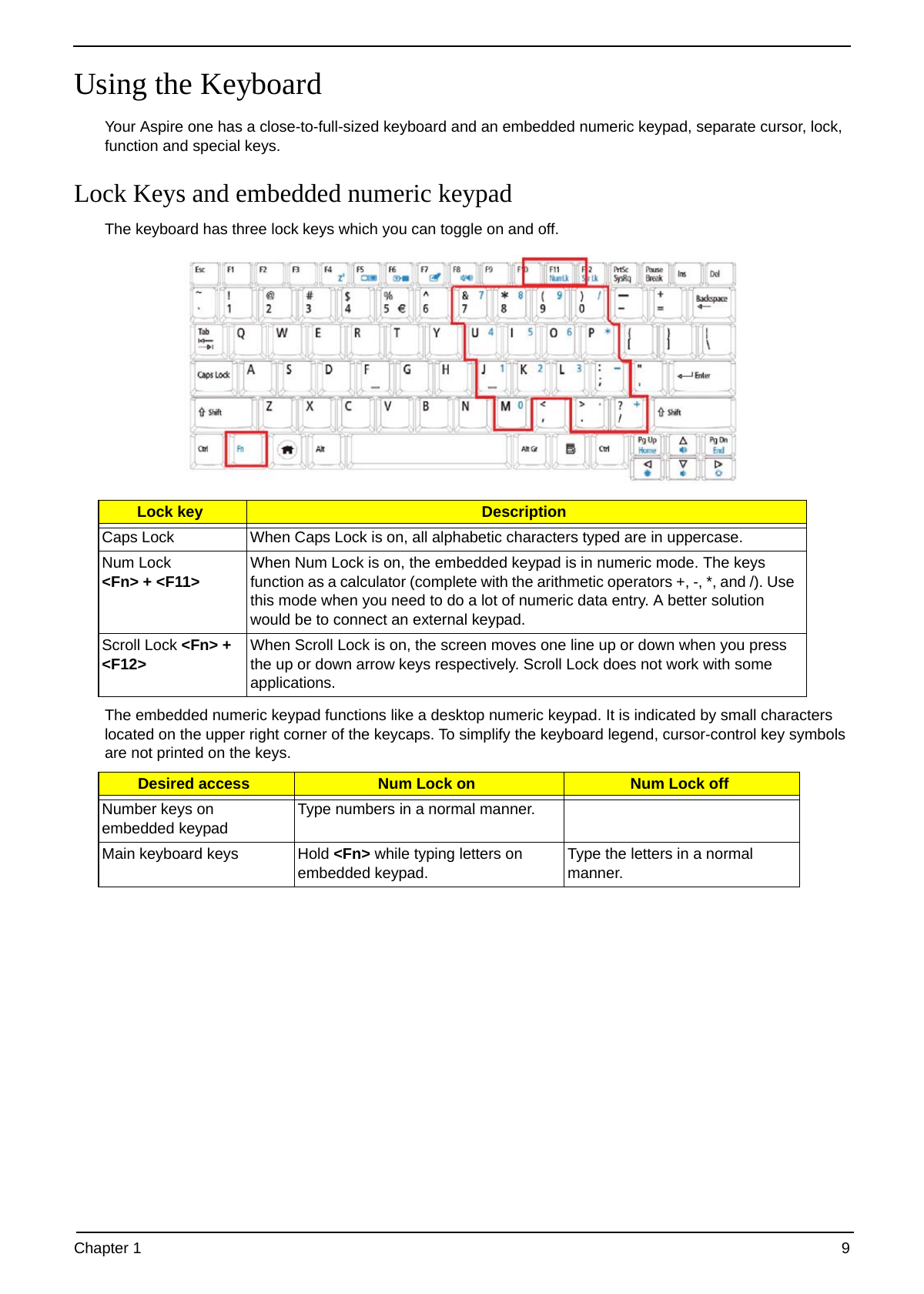
The keyboard has three lock keys which you can toggle on and off.
Lock key Description
Caps Lock When Caps Lock is on, all alphabetic characters typed are in uppercase.
Num Lock When Num Lock is on, the embedded keypad is in numeric mode. The keys
+ function as a calculator (complete with the arithmetic operators +, -, *, and /). Use
this mode when you need to do a lot of numeric data entry. A better solution
would be to connect an external keypad.
Scroll Lock + When Scroll Lock is on, the screen moves one line up or down when you press
the up or down arrow keys respectively. Scroll Lock does not work with some
applications.
The embedded numeric keypad functions like a desktop numeric keypad. It is indicated by small characters
located on the upper right corner of the keycaps. To simplify the keyboard legend, cursor-control key symbols
are not printed on the keys.
Desired access Num Lock on Num Lock off
Number keys on Type numbers in a normal manner.
embedded keypad
Main keyboard keys Hold while typing letters on Type the letters in a normal
embedded keypad. manner.
Chapter 1 9
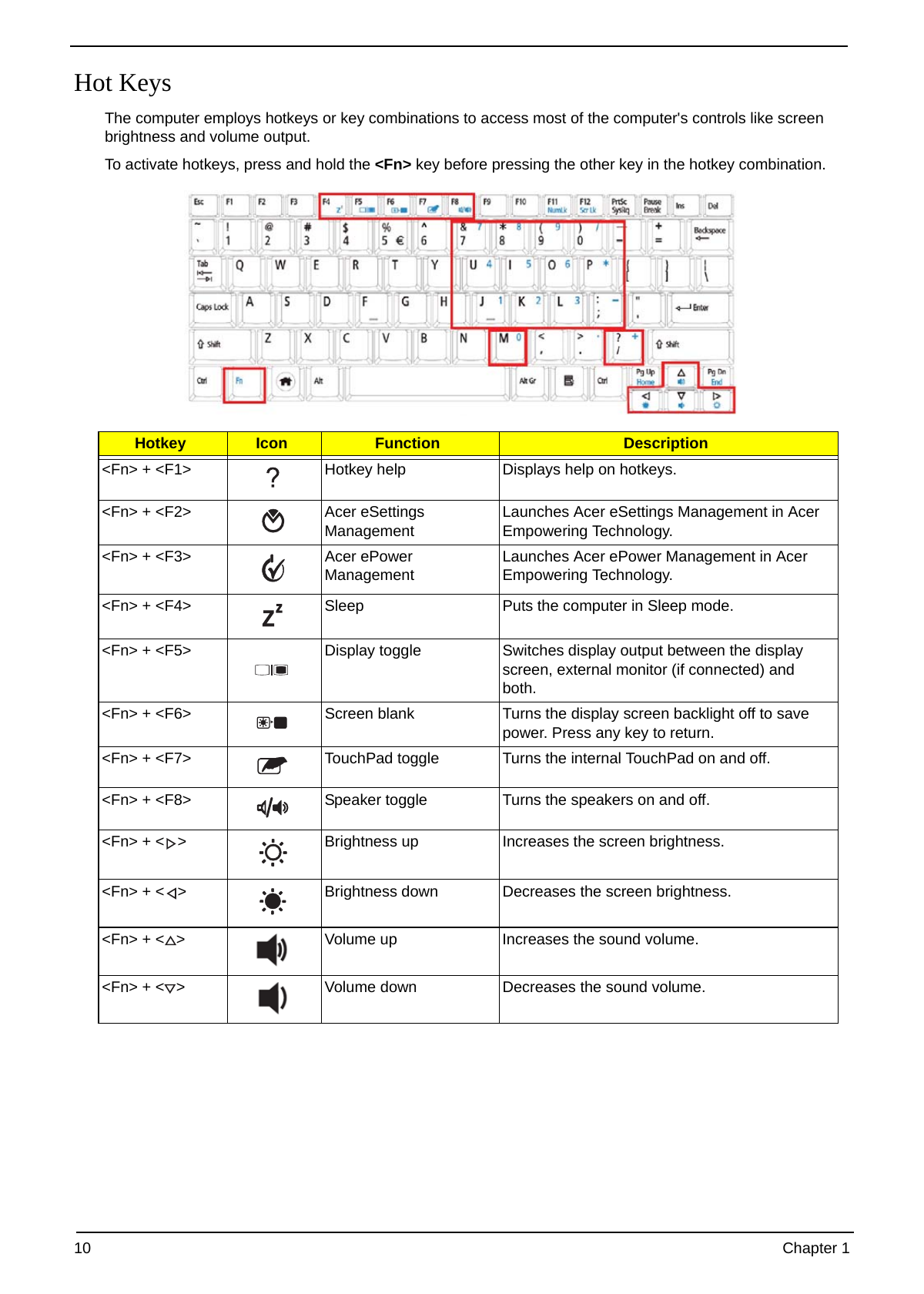
Hot Keys
The computer employs hotkeys or key combinations to access most of the computer's controls like screen
brightness and volume output.
To activate hotkeys, press and hold the key before pressing the other key in the hotkey combination.
Hotkey Icon Function Description
+ Hotkey help Displays help on hotkeys.
+ Acer eSettings Launches Acer eSettings Management in Acer
Management Empowering Technology.
+ Acer ePower Launches Acer ePower Management in Acer
Management Empowering Technology.
+ Sleep Puts the computer in Sleep mode.
+ Display toggle Switches display output between the display
screen, external monitor (if connected) and
both.
+ Screen blank Turns the display screen backlight off to save
power. Press any key to return.
+ TouchPad toggle Turns the internal TouchPad on and off.
+ Speaker toggle Turns the speakers on and off.
+ < > Brightness up Increases the screen brightness.
+ < > Brightness down Decreases the screen brightness.
+ < > Volume up Increases the sound volume.
+ < > Volume down Decreases the sound volume.
10 Chapter 1
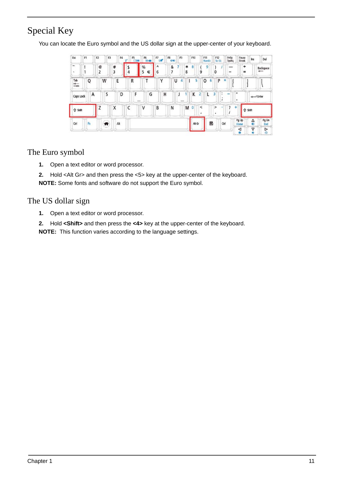
Special Key
You can locate the Euro symbol and the US dollar sign at the upper-center of your keyboard.
The Euro symbol
1. Open a text editor or word processor.
2. Hold and then press the <5> key at the upper-center of the keyboard.
NOTE: Some fonts and software do not support the Euro symbol.
The US dollar sign
1. Open a text editor or word processor.
2. Hold and then press the <4> key at the upper-center of the keyboard.
NOTE: This function varies according to the language settings.
Chapter 1 11
Using the System Utilities
Acer Bio-Protection (only for certain models) Acer Bio-Protection Fingerprint Solution is a multi-purpose
fingerprint software package integrated with the Microsoft Windows operating system. Utilizing the uniqueness
of one's fingerprint features, Acer Bio-Protection Fingerprint Solution has incorporated protection against
unauthorized access to your computer with centralized password management with Password Bank, easy
music player launching with Acer MusicLaunch, secure Internet favorites via Acer MyLaunch, and fast
application/website launching and login with Acer FingerLaunch, while Acer ProfileLaunch can launch up to
three applications/websites from a single finger swipe.
Acer Bio-Protection Fingerprint Solution also allows you to navigate through web browsers and documents
using Acer FingerNav. With Acer Bio-Protection Fingerprint Solution, you can now enjoy an extra layer of
protection for your personal computer, as well as the convenience of accessing your daily tasks with a simple
swipe of your finger!
For more information refer to the Acer Bio-Protection help files.
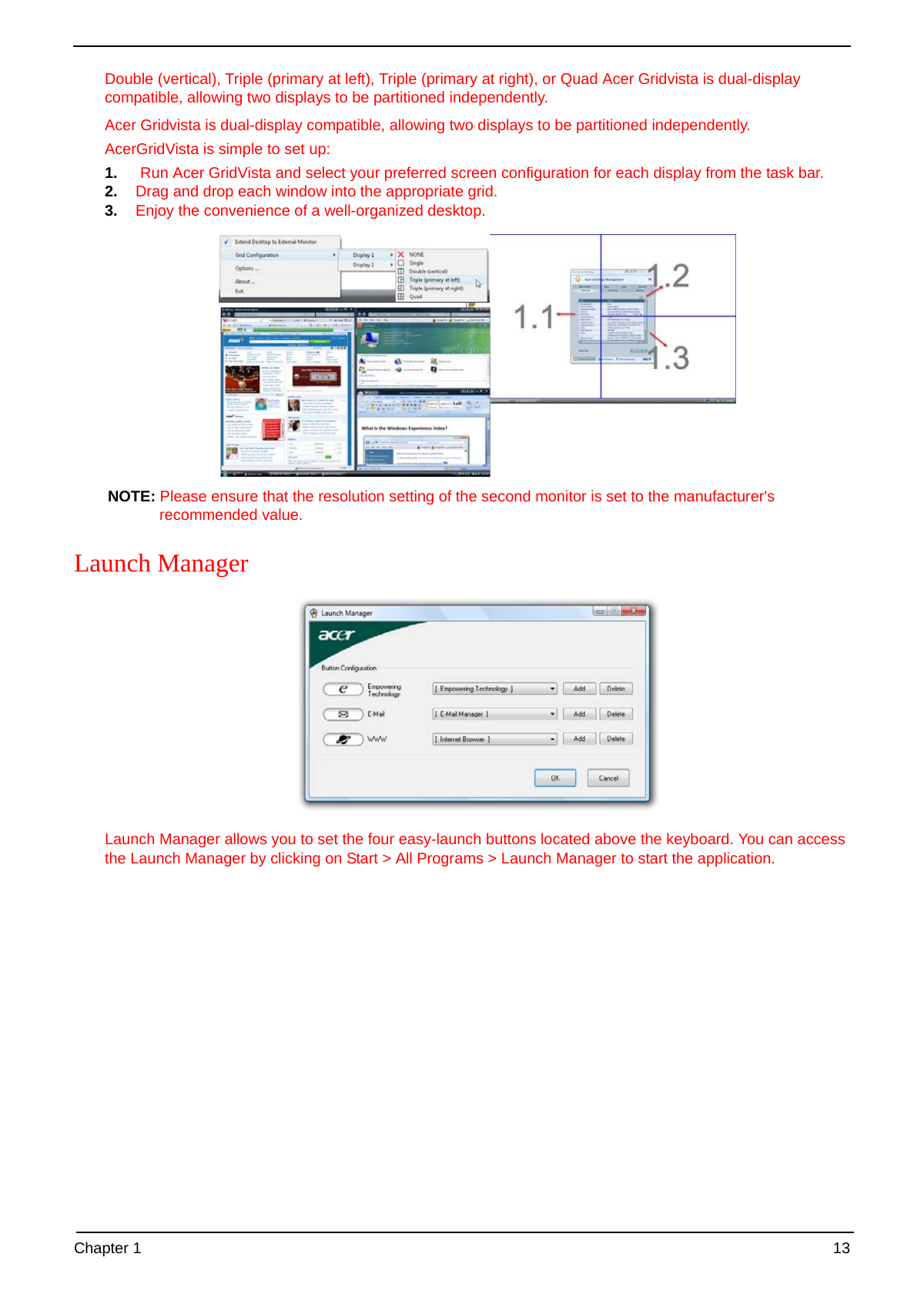
Acer GridVista (dual-display compatible)
NOTE: This feature is only available on certain models.
To enable the dual monitor feature of the notebook, first ensure that the second monitor is connected, then
select Start, Control Panel, Display and click on Settings. Select the secondary monitor (2) icon in the
display box and then click the check box Extend my windows desktop onto this monitor. Finally, click
Apply to confirm the new settings and click OK to complete the process.
Acer GridVista is a handy utility that offers four pre-defined display settings so you can view multiple windows
on the same screen. To access this function, please go to Start´ All Programs and click on Acer GridVista.
You may choose any one of the four display settings indicated below:
12 Chapter 1
Double (vertical), Triple (primary at left), Triple (primary at right), or Quad Acer Gridvista is dual-display
compatible, allowing two displays to be partitioned independently.
Acer Gridvista is dual-display compatible, allowing two displays to be partitioned independently.
AcerGridVista is simple to set up:
1. Run Acer GridVista and select your preferred screen configuration for each display from the task bar.
2. Drag and drop each window into the appropriate grid.
3. Enjoy the convenience of a well-organized desktop.
NOTE: Please ensure that the resolution setting of the second monitor is set to the manufacturer's
recommended value.
Launch Manager
Launch Manager allows you to set the four easy-launch buttons located above the keyboard. You can access
the Launch Manager by clicking on Start > All Programs > Launch Manager to start the application.
Chapter 1 13
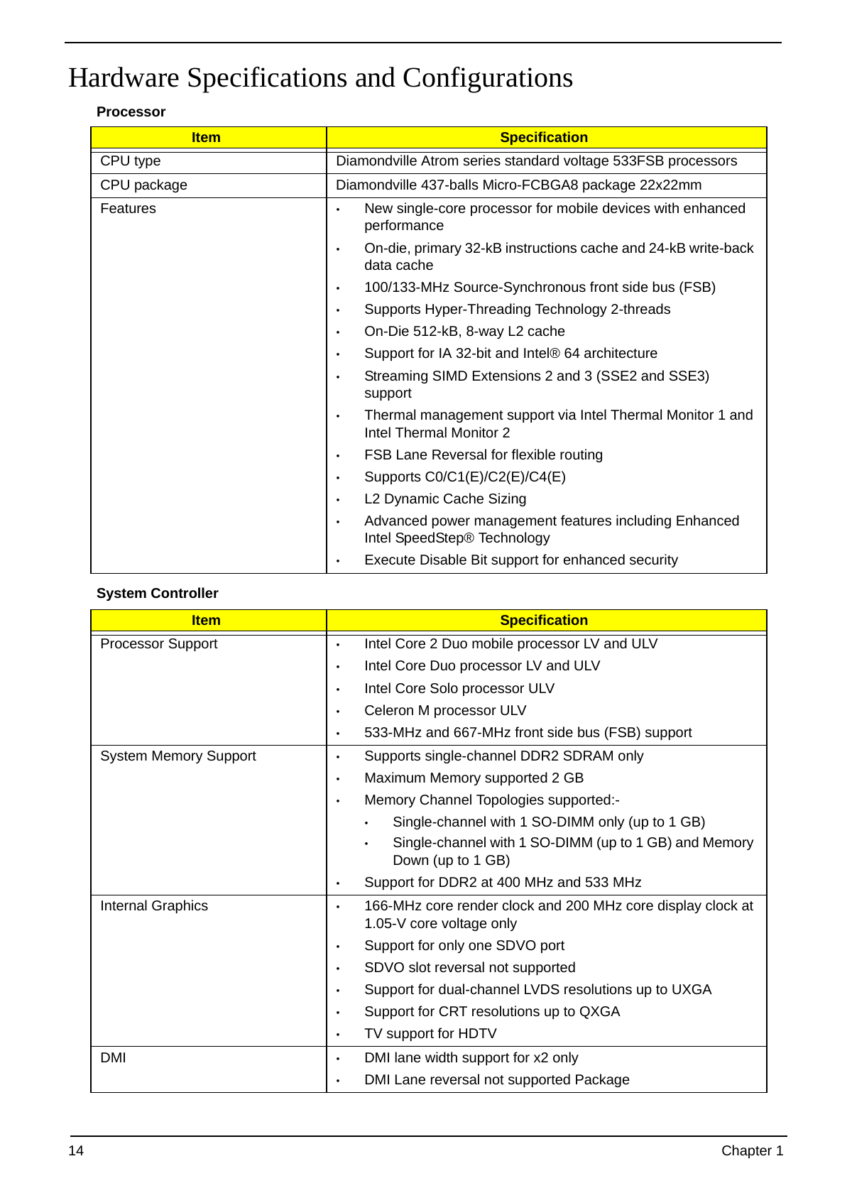
Hardware Specifications and Configurations
Processor
Item Specification
CPU type Diamondville Atrom series standard voltage 533FSB processors
CPU package Diamondville 437-balls Micro-FCBGA8 package 22x22mm
Features • New single-core processor for mobile devices with enhanced
performance
• On-die, primary 32-kB instructions cache and 24-kB write-back
data cache
• 100/133-MHz Source-Synchronous front side bus (FSB)
• Supports Hyper-Threading Technology 2-threads
• On-Die 512-kB, 8-way L2 cache
• Support for IA 32-bit and Intel® 64 architecture
• Streaming SIMD Extensions 2 and 3 (SSE2 and SSE3)
support
• Thermal management support via Intel Thermal Monitor 1 and
Intel Thermal Monitor 2
• FSB Lane Reversal for flexible routing
• Supports C0/C1(E)/C2(E)/C4(E)
• L2 Dynamic Cache Sizing
• Advanced power management features including Enhanced
Intel SpeedStep® Technology
• Execute Disable Bit support for enhanced security
System Controller
Item Specification
Processor Support • Intel Core 2 Duo mobile processor LV and ULV
• Intel Core Duo processor LV and ULV
• Intel Core Solo processor ULV
• Celeron M processor ULV
• 533-MHz and 667-MHz front side bus (FSB) support
System Memory Support • Supports single-channel DDR2 SDRAM only
• Maximum Memory supported 2 GB
• Memory Channel Topologies supported:-
• Single-channel with 1 SO-DIMM only (up to 1 GB)
• Single-channel with 1 SO-DIMM (up to 1 GB) and Memory
Down (up to 1 GB)
• Support for DDR2 at 400 MHz and 533 MHz
Internal Graphics • 166-MHz core render clock and 200 MHz core display clock at
1.05-V core voltage only
• Support for only one SDVO port
• SDVO slot reversal not supported
• Support for dual-channel LVDS resolutions up to UXGA
• Support for CRT resolutions up to QXGA
• TV support for HDTV
DMI • DMI lane width support for x2 only
• DMI Lane reversal not supported Package
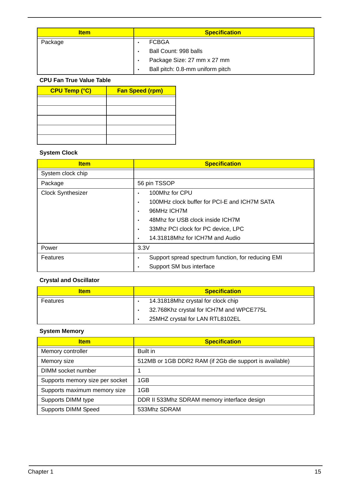
14 Chapter 1
Item Specification
Package • FCBGA
• Ball Count: 998 balls
• Package Size: 27 mm x 27 mm
• Ball pitch: 0.8-mm uniform pitch
CPU Fan True Value Table
CPU Temp (°C) Fan Speed (rpm)
System Clock
Item Specification
System clock chip
Package 56 pin TSSOP
Clock Synthesizer • 100Mhz for CPU
• 100MHz clock buffer for PCI-E and ICH7M SATA
• 96MHz ICH7M
• 48Mhz for USB clock inside ICH7M
• 33Mhz PCI clock for PC device, LPC
• 14.31818Mhz for ICH7M and Audio
Power 3.3V
Features • Support spread spectrum function, for reducing EMI
• Support SM bus interface
Crystal and Oscillator
Item Specification
Features • 14.31818Mhz crystal for clock chip
• 32.768Khz crystal for ICH7M and WPCE775L
• 25MHZ crystal for LAN RTL8102EL
System Memory
Item Specification
Memory controller Built in
Memory size 512MB or 1GB DDR2 RAM (if 2Gb die support is available)
DIMM socket number 1
Supports memory size per socket 1GB
Supports maximum memory size 1GB
Supports DIMM type DDR II 533Mhz SDRAM memory interface design
Supports DIMM Speed 533Mhz SDRAM
Chapter 1 15
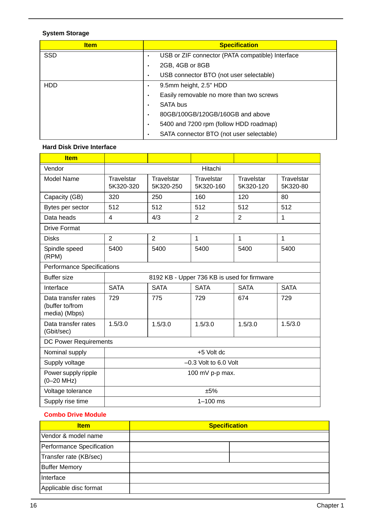
System Storage
Item Specification
SSD • USB or ZIF connector (PATA compatible) Interface
• 2GB, 4GB or 8GB
• USB connector BTO (not user selectable)
HDD • 9.5mm height, 2.5" HDD
• Easily removable no more than two screws
• SATA bus
• 80GB/100GB/120GB/160GB and above
• 5400 and 7200 rpm (follow HDD roadmap)
• SATA connector BTO (not user selectable)
Hard Disk Drive Interface
Item
Vendor Hitachi
Model Name Travelstar Travelstar Travelstar Travelstar Travelstar
5K320-320 5K320-250 5K320-160 5K320-120 5K320-80
Capacity (GB) 320 250 160 120 80
Bytes per sector 512 512 512 512 512
Data heads 4 4/3 2 2 1
Drive Format
Disks 2 2 1 1 1
Spindle speed 5400 5400 5400 5400 5400
(RPM)
Performance Specifications
Buffer size 8192 KB - Upper 736 KB is used for firmware
Interface SATA SATA SATA SATA SATA
Data transfer rates 729 775 729 674 729
(buffer to/from
media) (Mbps)
Data transfer rates 1.5/3.0 1.5/3.0 1.5/3.0 1.5/3.0 1.5/3.0
(Gbit/sec)
DC Power Requirements
Nominal supply +5 Volt dc
Supply voltage –0.3 Volt to 6.0 Volt
Power supply ripple 100 mV p-p max.
(0–20 MHz)
Voltage tolerance ±5%
Supply rise time 1–100 ms
Combo Drive Module
Item Specification
Vendor & model name
Performance Specification
Transfer rate (KB/sec)
Buffer Memory
Interface
Applicable disc format
16 Chapter 1
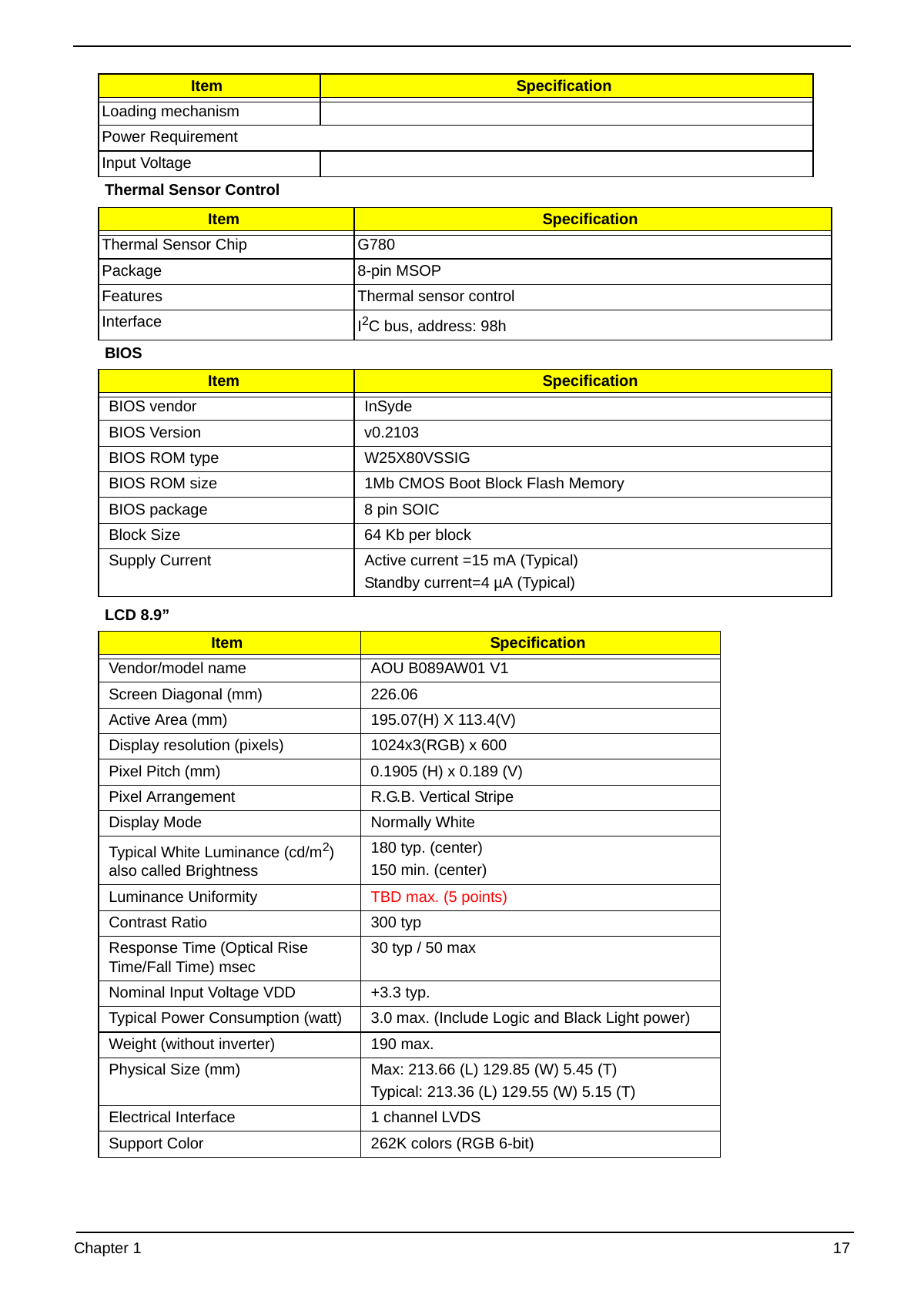
Item Specification
Loading mechanism
Power Requirement
Input Voltage
Thermal Sensor Control
Item Specification
Thermal Sensor Chip G780
Package 8-pin MSOP
Features Thermal sensor control
Interface I2C bus, address: 98h
BIOS
Item Specification
BIOS vendor InSyde
BIOS Version v0.2103
BIOS ROM type W25X80VSSIG
BIOS ROM size 1Mb CMOS Boot Block Flash Memory
BIOS package 8 pin SOIC
Block Size 64 Kb per block
Supply Current Active current =15 mA (Typical)
Standby current=4 µA (Typical)
LCD 8.9”
Item Specification
Vendor/model name AOU B089AW01 V1
Screen Diagonal (mm) 226.06
Active Area (mm) 195.07(H) X 113.4(V)
Display resolution (pixels) 1024x3(RGB) x 600
Pixel Pitch (mm) 0.1905 (H) x 0.189 (V)
Pixel Arrangement R.G.B. Vertical Stripe
Display Mode Normally White
Typical White Luminance (cd/m2) 180 typ. (center)
also called Brightness 150 min. (center)
Luminance Uniformity TBD max. (5 points)
Contrast Ratio 300 typ
Response Time (Optical Rise 30 typ / 50 max
Time/Fall Time) msec
Nominal Input Voltage VDD +3.3 typ.
Typical Power Consumption (watt) 3.0 max. (Include Logic and Black Light power)
Weight (without inverter) 190 max.
Physical Size (mm) Max: 213.66 (L) 129.85 (W) 5.45 (T)
Typical: 213.36 (L) 129.55 (W) 5.15 (T)
Electrical Interface 1 channel LVDS
Support Color 262K colors (RGB 6-bit)
Chapter 1 17
Item Specification
Viewing Angle (degree)
Horizontal (Right) CR = 10 (Left) 45, 45
Vertical (Upper) CR = 10 (Lower) 15, 35
Temperature Range (°C)
Operating 0 to +50
Storage (shipping) -20 to +65
RoHS Compliance RoHS Compliance
KBC
Item Specification
Chipset WPCE775L
Features • Host interface, base on Intel's LPC Interface specification
Revision 1.0
• PC01 REV 0.3 and ACPI 1.0b compliant
• 16-bit RISC core, with 2 Mbyte address space, and
running at up to 20 MHZ
• Software and Hardware controlled clock throttling
• Share BIOS flash memory (internal and/or external)
• Y2K- compliant
• 84 GPIO ports with variety of wake-up events
• Extremely low current consumption in idle mode
• JTAG-base debugger interface
• 176 pin LQFP package
Audio Codec and Amplifier
Item Specification
Audio Controller Realtek ALC268 Azadia Codec and Amplifier G1441
Features • HD Audio
• SNR > 85, High-performance DACs with 95dB SNR (A-
Weighting), ADCs with 85dB SNR (A-Weighting)
• Internal Digital Microphone
• Two speakers, at least 1.0W for each
• 1* Analog Microphone, 1*Headphone jack
LAN Interface
Item Specification
LAN Chipset Realtek solution RTL8102EL
Features • Support WOL from S53
• File deployment support
• LDCM support
Keyboard
Item Specification
Type New Acer flat keyboard
Total number of keypads 84
Windows logo key Yes
Internal & external keyboard work Plug USB keyboard to the USB port directly: Yes
simultaneously
18 Chapter 1
Mini Card
Item Specification
Number Supported 2
Features • 2 mini card slot (1 for 3G and 1 for WLAN or WLAN/
WiMax)
• Embedded 3G module and built-in 1 antenna (combo-
wireless+3G) on top/side of LCD
Camera
Item Specification
Maximum Module Form Factor 65*8*4.74 mm3
Sensor Type and Resolution Color CMOS, VGA(640x480)
ISP USB 2.0 high speed
Focusing Type Fix Focus
F/N 2.8±5%
Focusing Range 30 cm ~infinity (theory) focus at 48 cm
Format of Image Output Data YUV
Frame Rate VGA: 30 fps (MAX.) @USB2.0 high speed
Operation Voltage Total Supply Voltage: 3.3V
ISP: 3.3, 1.8V
CMOS Sensor: 2.8V, 1.8V
System Interfacing USB 2.0 (High Speed)
Board Connector Type Wire to board 5-pin connector
PCB layer 4 layers
Power consumption Operation: Around 400mW @VGA 30fps
Suspend: < 500uA in Vista
Weight 1.8 g
3G Card
Item Specification
Type
Features • 3G card in mini-PCI card size
• Control by USB interface
• User accessible SIM card by battery remove
• Antenna: Has to be placed on the sides of LCD in A/B
cover
Wireless LAN
Item Specification
Type
Features • Manufacturing option: mini-card
• 802.11b/g (3rd Party)
• Built-in 2 Antenna
• Antenna: Has to be placed on the top of LCD on the
sides of LCD latch
Chapter 1 19
WLAN/WiMAX Dual-mode Card
Item Specification
Type
Features • WLAN/WiMax card in mini-PCI card size
• WLAN controlled by PCIe interface
• WiMax controlled by USB interface
Battery
Item Specification
Vendor & model name
Battery Type
Pack capacity
Number of battery cell
Package configuration
Normal voltage
Charge voltage
20 Chapter 1
Chapter 2
System Utilities
BIOS Setup Utility
The BIOS Setup Utility is a hardware configuration program built into your computer’s BIOS (Basic Input/
Output System).
Your computer is already properly configured and optimized, and you do not need to run this utility. However, if
you encounter configuration problems, you may need to run Setup. Please also refer to Chapter 4
Troubleshooting when problem arises.
To activate the BIOS Utility, press F2 during POST (when “Press to enter Setup” message is prompted
on the bottom of screen).
Press F2 to enter setup. The default parameter of F12 Boot Menu is set to “disabled”. If you want to change
boot device without entering BIOS Setup Utility, please set the parameter to “enabled”.
Press during POST to enter multi-boot menu. In this menu, user can change boot device without
entering BIOS SETUP Utility.
Navigating the BIOS Utility
There are six menu options: Information, Main, Advanced, Security, Boot, and Exit.
Follow these instructions:
• To choose a menu, use the left and right arrow keys.
• To choose an item, use the up and down arrow keys.
• To change the value of a parameter, press F5 or F6.
• A plus sign (+) indicates the item has sub-items. Press Enter to expand this item.
• Press Esc while you are in any of the menu options to go to the Exit menu.
• In any menu, you can load default settings by pressing F9. You can also press F10 to save any
changes made and exit the BIOS Setup Utility.
NOTE: You can change the value of a parameter if it is enclosed in square brackets. Navigation keys for a
particular menu are shown on the bottom of the screen. Help for parameters are found in the Item
Specific Help part of the screen. Read this carefully when making changes to parameter values. Please
note that system information is subject to different models.
Chapter 2 21
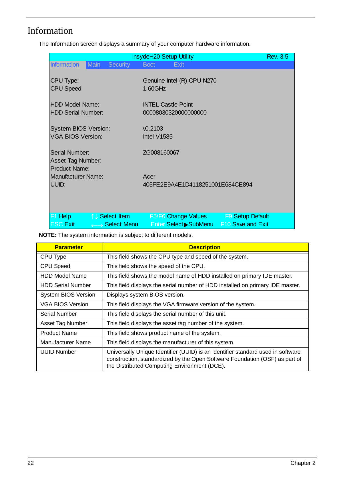
Information
The Information screen displays a summary of your computer hardware information.
InsydeH20 Setup Utility Rev. 3.5
Information Main Security Boot Exit
CPU Type: Genuine Intel (R) CPU N270
CPU Speed: 1.60GHz
HDD Model Name: INTEL Castle Point
HDD Serial Number: 00008030320000000000
System BIOS Version: v0.2103
VGA BIOS Version: Intel V1585
Serial Number: ZG008160067
Asset Tag Number:
Product Name:
Manufacturer Name: Acer
UUID: 405FE2E9A4E1D4118251001E684CE894
F1 Help ↑↓ Select Item F5/F6 Change Values F9 Setup Default
ESC Exit ←→ Select Menu Enter SelectXSubMenu F10 Save and Exit
NOTE: The system information is subject to different models.
Parameter Description
CPU Type This field shows the CPU type and speed of the system.
CPU Speed This field shows the speed of the CPU.
HDD Model Name This field shows the model name of HDD installed on primary IDE master.
HDD Serial Number This field displays the serial number of HDD installed on primary IDE master.
System BIOS Version Displays system BIOS version.
VGA BIOS Version This field displays the VGA firmware version of the system.
Serial Number This field displays the serial number of this unit.
Asset Tag Number This field displays the asset tag number of the system.
Product Name This field shows product name of the system.
Manufacturer Name This field displays the manufacturer of this system.
UUID Number Universally Unique Identifier (UUID) is an identifier standard used in software
construction, standardized by the Open Software Foundation (OSF) as part of
the Distributed Computing Environment (DCE).
22 Chapter 2
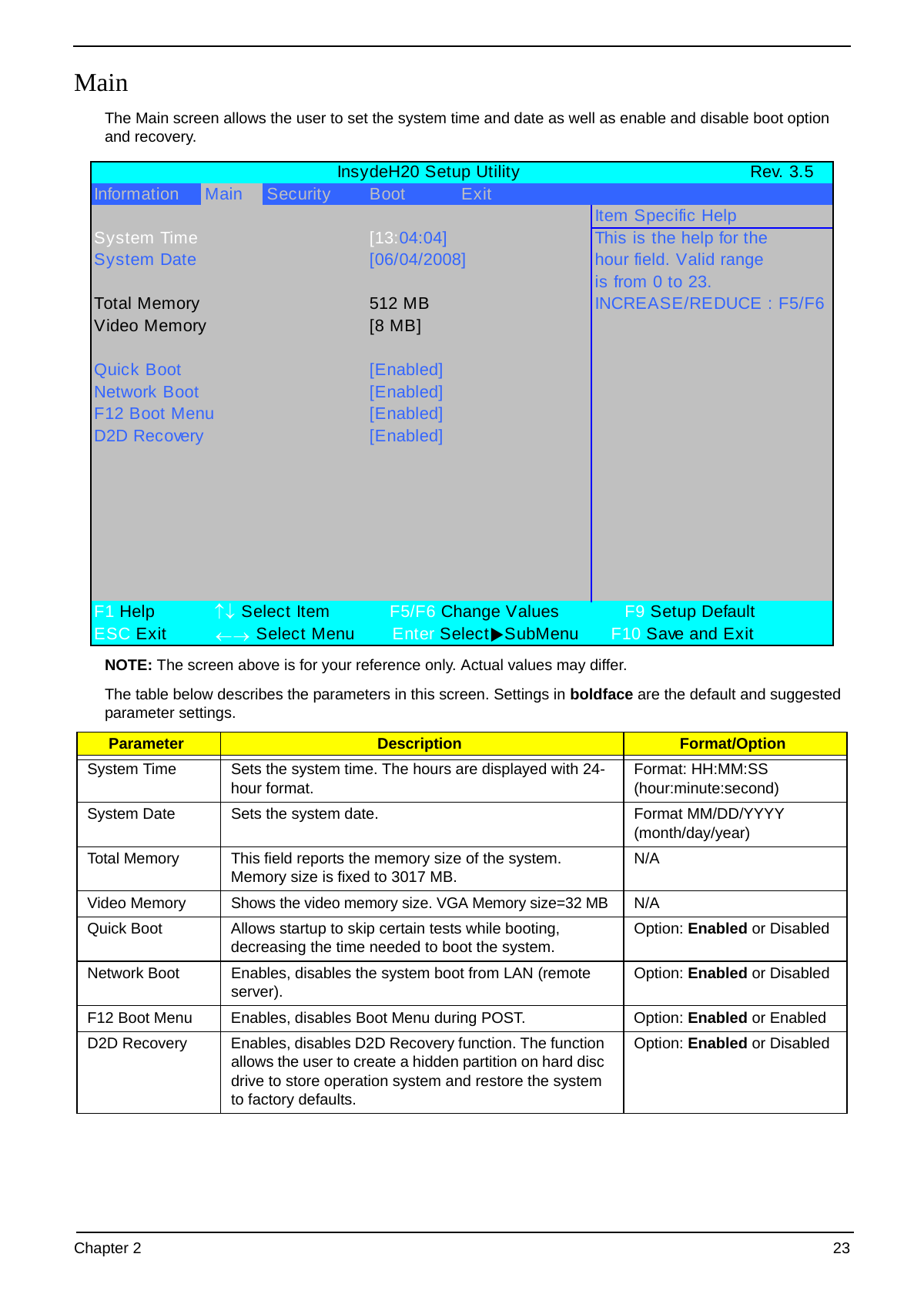
Main
The Main screen allows the user to set the system time and date as well as enable and disable boot option
and recovery.
InsydeH20 Setup Utility Rev. 3.5
Information Main Security Boot Exit
Item Specific Help
System Time [13:04:04] This is the help for the
System Date [06/04/2008] hour field. Valid range
is from 0 to 23.
Total Memory 512 MB INCREASE/REDUCE : F5/F6
Video Memory [8 MB]
Quick Boot [Enabled]
Network Boot [Enabled]
F12 Boot Menu [Enabled]
D2D Recovery [Enabled]
F1 Help ↑↓ Select Item F5/F6 Change Values F9 Setup Default
ESC Exit ←→ Select Menu Enter Select XSubMenu F10 Save and Exit
NOTE: The screen above is for your reference only. Actual values may differ.
The table below describes the parameters in this screen. Settings in boldface are the default and suggested
parameter settings.
Parameter Description Format/Option
System Time Sets the system time. The hours are displayed with 24- Format: HH:MM:SS
hour format. (hour:minute:second)
System Date Sets the system date. Format MM/DD/YYYY
(month/day/year)
Total Memory This field reports the memory size of the system. N/A
Memory size is fixed to 3017 MB.
Video Memory Shows the video memory size. VGA Memory size=32 MB N/A
Quick Boot Allows startup to skip certain tests while booting, Option: Enabled or Disabled
decreasing the time needed to boot the system.
Network Boot Enables, disables the system boot from LAN (remote Option: Enabled or Disabled
server).
F12 Boot Menu Enables, disables Boot Menu during POST. Option: Enabled or Enabled
D2D Recovery Enables, disables D2D Recovery function. The function Option: Enabled or Disabled
allows the user to create a hidden partition on hard disc
drive to store operation system and restore the system
to factory defaults.
Chapter 2 23
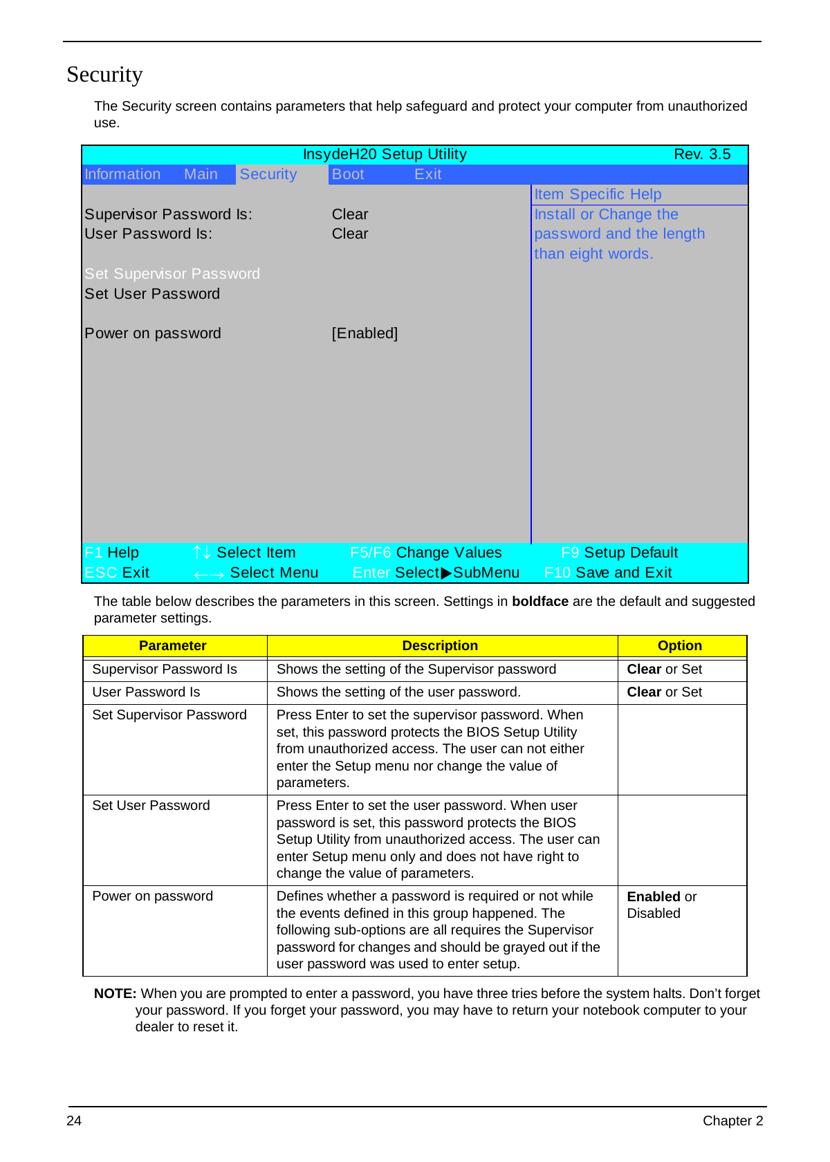
Security
The Security screen contains parameters that help safeguard and protect your computer from unauthorized
use.
InsydeH20 Setup Utility Rev. 3.5
Information Main Security Boot Exit
Item Specific Help
Supervisor Password Is: Clear Install or Change the
User Password Is: Clear password and the length
than eight words.
Set Supervisor Password
Set User Password
Power on password [Enabled]
F1 Help ↑↓ Select Item F5/F6 Change Values F9 Setup Default
ESC Exit ←→ Select Menu Enter Select XSubMenu F10 Save and Exit
The table below describes the parameters in this screen. Settings in boldface are the default and suggested
parameter settings.
Parameter Description Option
Supervisor Password Is Shows the setting of the Supervisor password Clear or Set
User Password Is Shows the setting of the user password. Clear or Set
Set Supervisor Password Press Enter to set the supervisor password. When
set, this password protects the BIOS Setup Utility
from unauthorized access. The user can not either
enter the Setup menu nor change the value of
parameters.
Set User Password Press Enter to set the user password. When user
password is set, this password protects the BIOS
Setup Utility from unauthorized access. The user can
enter Setup menu only and does not have right to
change the value of parameters.
Power on password Defines whether a password is required or not while Enabled or
the events defined in this group happened. The Disabled
following sub-options are all requires the Supervisor
password for changes and should be grayed out if the
user password was used to enter setup.
NOTE: When you are prompted to enter a password, you have three tries before the system halts. Don’t forget
your password. If you forget your password, you may have to return your notebook computer to your
dealer to reset it.
24 Chapter 2
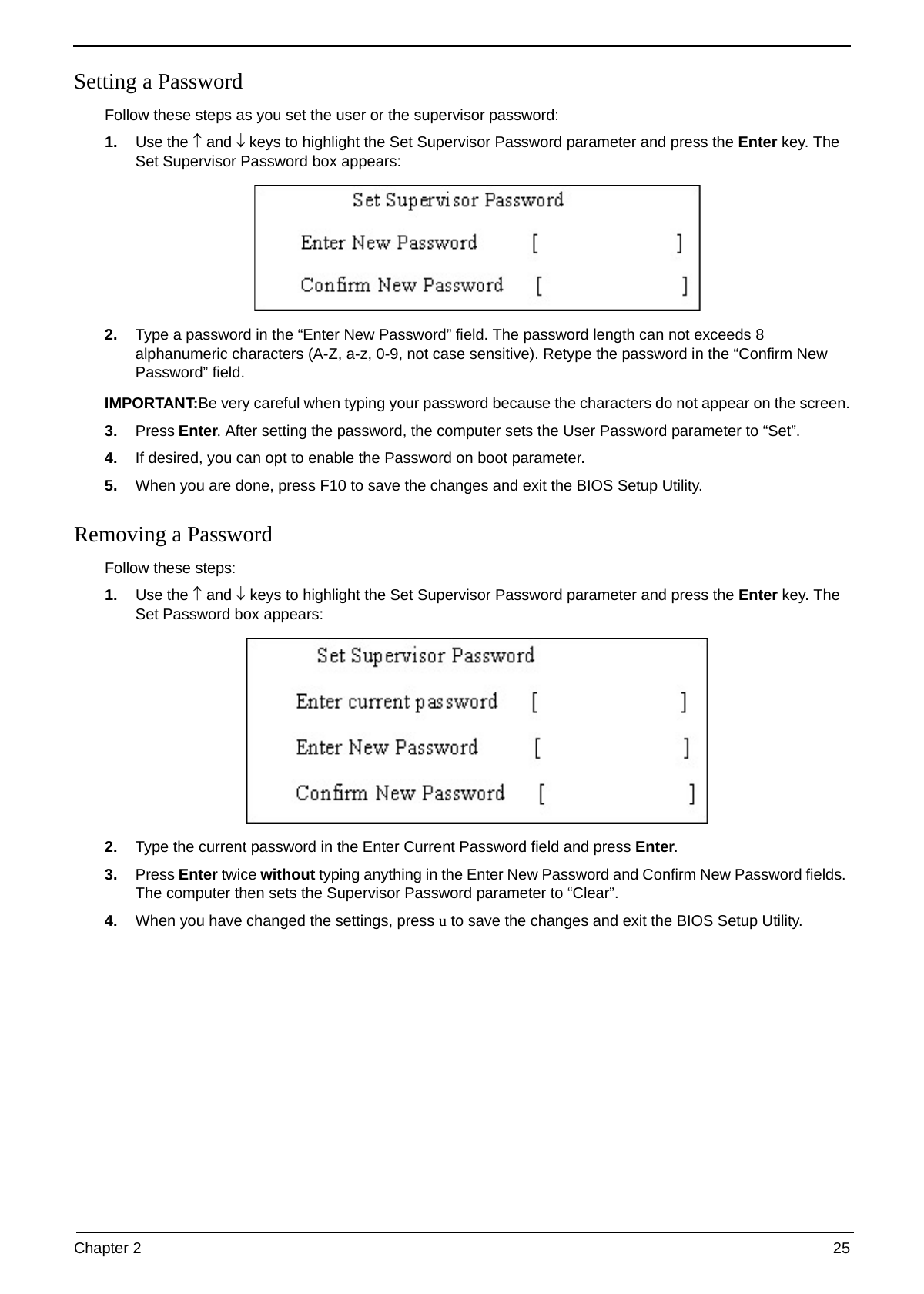
Setting a Password
Follow these steps as you set the user or the supervisor password:
1. Use the ↑ and ↓ keys to highlight the Set Supervisor Password parameter and press the Enter key. The
Set Supervisor Password box appears:
2. Type a password in the “Enter New Password” field. The password length can not exceeds 8
alphanumeric characters (A-Z, a-z, 0-9, not case sensitive). Retype the password in the “Confirm New
Password” field.
IMPORTANT:Be very careful when typing your password because the characters do not appear on the screen.
3. Press Enter. After setting the password, the computer sets the User Password parameter to “Set”.
4. If desired, you can opt to enable the Password on boot parameter.
5. When you are done, press F10 to save the changes and exit the BIOS Setup Utility.
Removing a Password
Follow these steps:
1. Use the ↑ and ↓ keys to highlight the Set Supervisor Password parameter and press the Enter key. The
Set Password box appears:
2. Type the current password in the Enter Current Password field and press Enter.
3. Press Enter twice without typing anything in the Enter New Password and Confirm New Password fields.
The computer then sets the Supervisor Password parameter to “Clear”.
4. When you have changed the settings, press u to save the changes and exit the BIOS Setup Utility.
Chapter 2 25
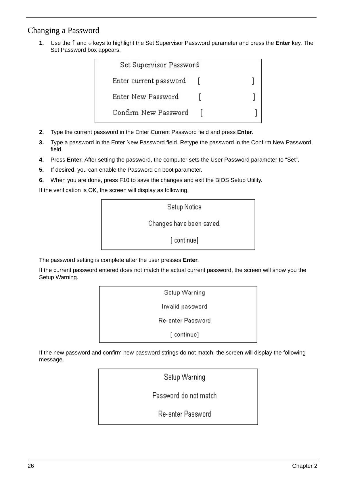
Changing a Password
1. Use the ↑ and ↓ keys to highlight the Set Supervisor Password parameter and press the Enter key. The
Set Password box appears.
2. Type the current password in the Enter Current Password field and press Enter.
3. Type a password in the Enter New Password field. Retype the password in the Confirm New Password
field.
4. Press Enter. After setting the password, the computer sets the User Password parameter to “Set”.
5. If desired, you can enable the Password on boot parameter.
6. When you are done, press F10 to save the changes and exit the BIOS Setup Utility.
If the verification is OK, the screen will display as following.
The password setting is complete after the user presses Enter.
If the current password entered does not match the actual current password, the screen will show you the
Setup Warning.
If the new password and confirm new password strings do not match, the screen will display the following
message.
26 Chapter 2
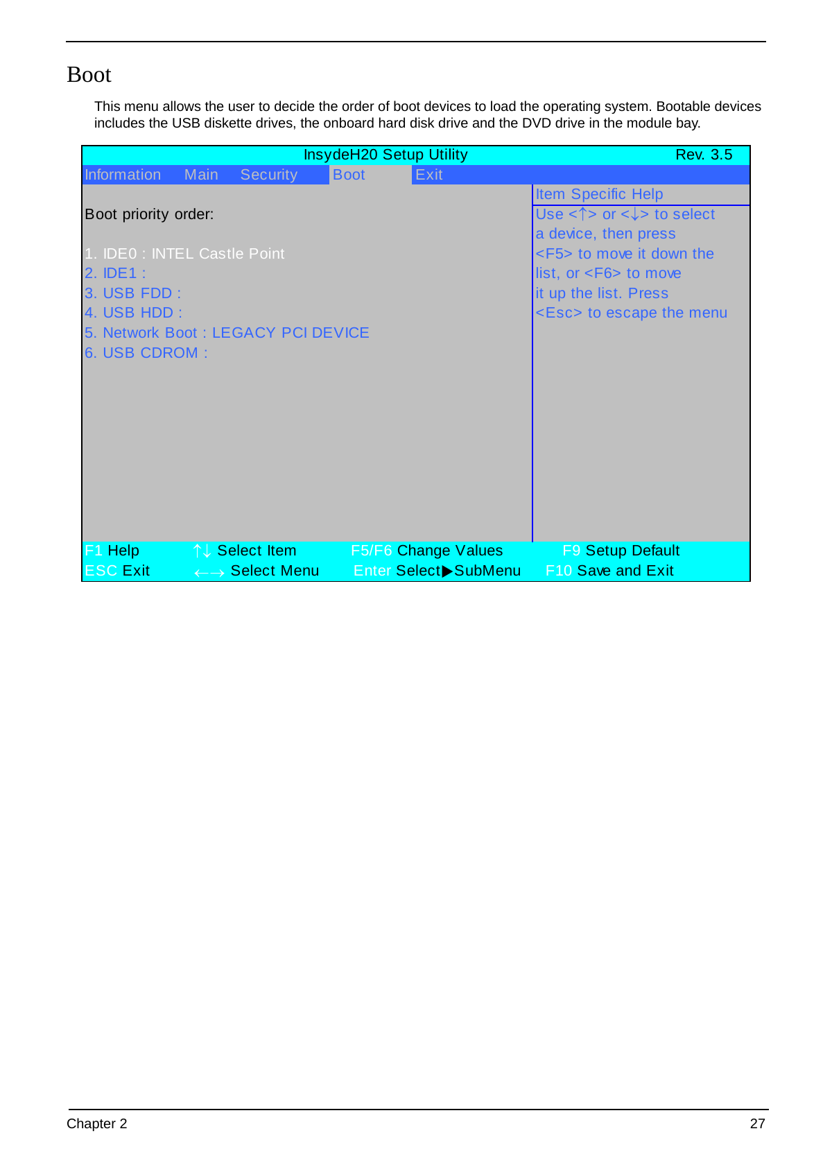
Boot
This menu allows the user to decide the order of boot devices to load the operating system. Bootable devices
includes the USB diskette drives, the onboard hard disk drive and the DVD drive in the module bay.
InsydeH20 Setup Utility Rev. 3.5
Information Main Security Boot Exit
Item Specific Help
Boot priority order: Use < ↑ > or < ↓ > to select
a device, then press
1. IDE0 : INTEL Castle Point to move it down the
2. IDE1 : list, or to move
3. USB FDD : it up the list. Press
4. USB HDD : to escape the menu
5. Network Boot : LEGACY PCI DEVICE
6. USB CDROM :
F1 Help ↑↓ Select Item F5/F6 Change Values F9 Setup Default
ESC Exit ←→ Select Menu Enter Select XSubMenu F10 Save and Exit
Chapter 2 27
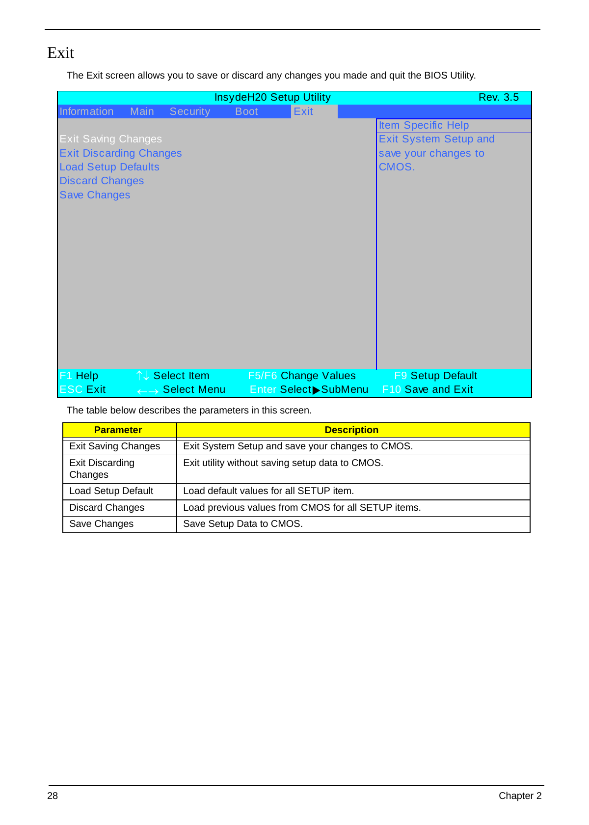
Exit
The Exit screen allows you to save or discard any changes you made and quit the BIOS Utility.
InsydeH20 Setup Utility Rev. 3.5
Information Main Security Boot Exit
Item Specific Help
Exit Saving Changes Exit System Setup and
Exit Discarding Changes save your changes to
Load Setup Defaults CMOS.
Discard Changes
Save Changes
F1 Help ↑↓ Select Item F5/F6 Change Values F9 Setup Default
ESC Exit ←→ Select Menu Enter Select XSubMenu F10 Save and Exit
The table below describes the parameters in this screen.
Parameter Description
Exit Saving Changes Exit System Setup and save your changes to CMOS.
Exit Discarding Exit utility without saving setup data to CMOS.
Changes
Load Setup Default Load default values for all SETUP item.
Discard Changes Load previous values from CMOS for all SETUP items.
Save Changes Save Setup Data to CMOS.
28 Chapter 2
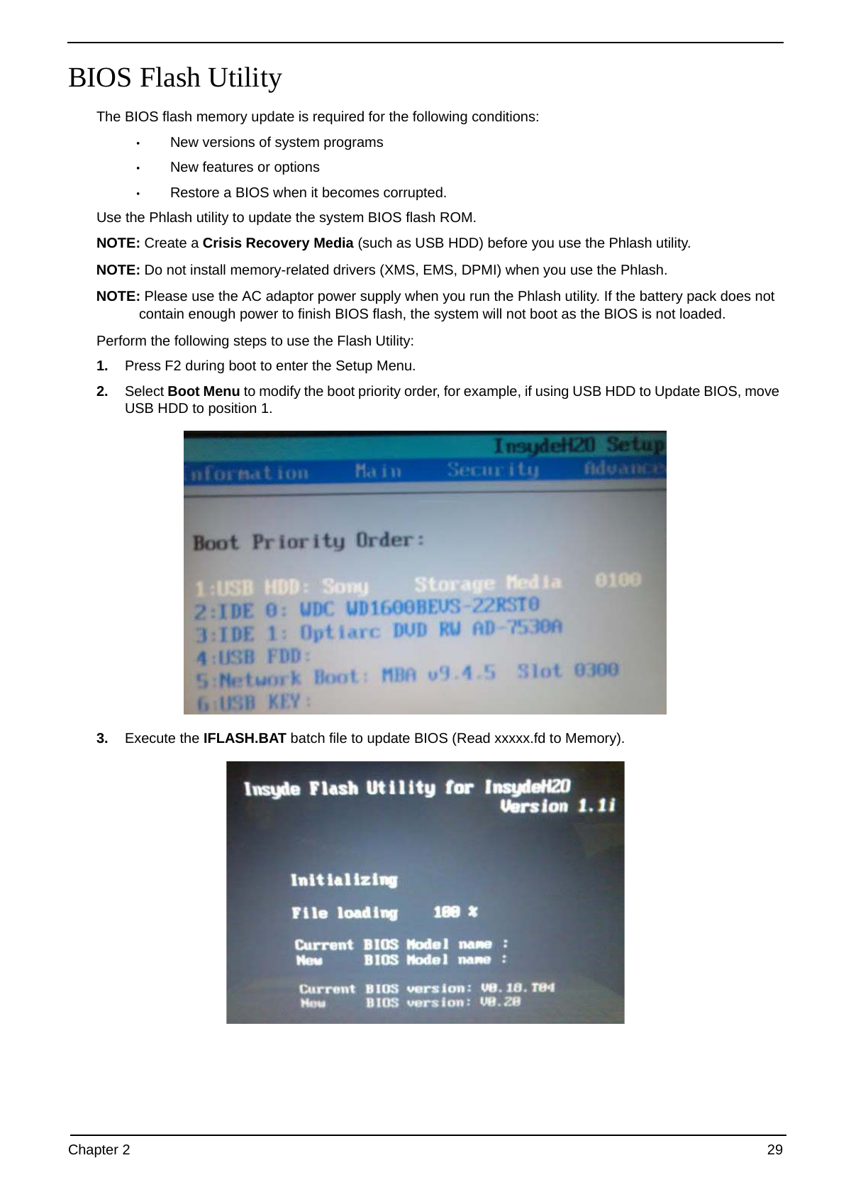
BIOS Flash Utility
The BIOS flash memory update is required for the following conditions:
• New versions of system programs
• New features or options
• Restore a BIOS when it becomes corrupted.
Use the Phlash utility to update the system BIOS flash ROM.
NOTE: Create a Crisis Recovery Media (such as USB HDD) before you use the Phlash utility.
NOTE: Do not install memory-related drivers (XMS, EMS, DPMI) when you use the Phlash.
NOTE: Please use the AC adaptor power supply when you run the Phlash utility. If the battery pack does not
contain enough power to finish BIOS flash, the system will not boot as the BIOS is not loaded.
Perform the following steps to use the Flash Utility:
1. Press F2 during boot to enter the Setup Menu.
2. Select Boot Menu to modify the boot priority order, for example, if using USB HDD to Update BIOS, move
USB HDD to position 1.
3. Execute the IFLASH.BAT batch file to update BIOS (Read xxxxx.fd to Memory).
Chapter 2 29
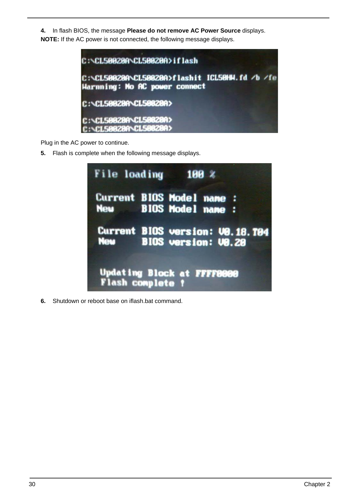
4. In flash BIOS, the message Please do not remove AC Power Source displays.
NOTE: If the AC power is not connected, the following message displays.
Plug in the AC power to continue.
5. Flash is complete when the following message displays.
6. Shutdown or reboot base on iflash.bat command.
30 Chapter 2
Remove HDD/BIOS Utility
This section provide you with removing HDD/BIOS method:
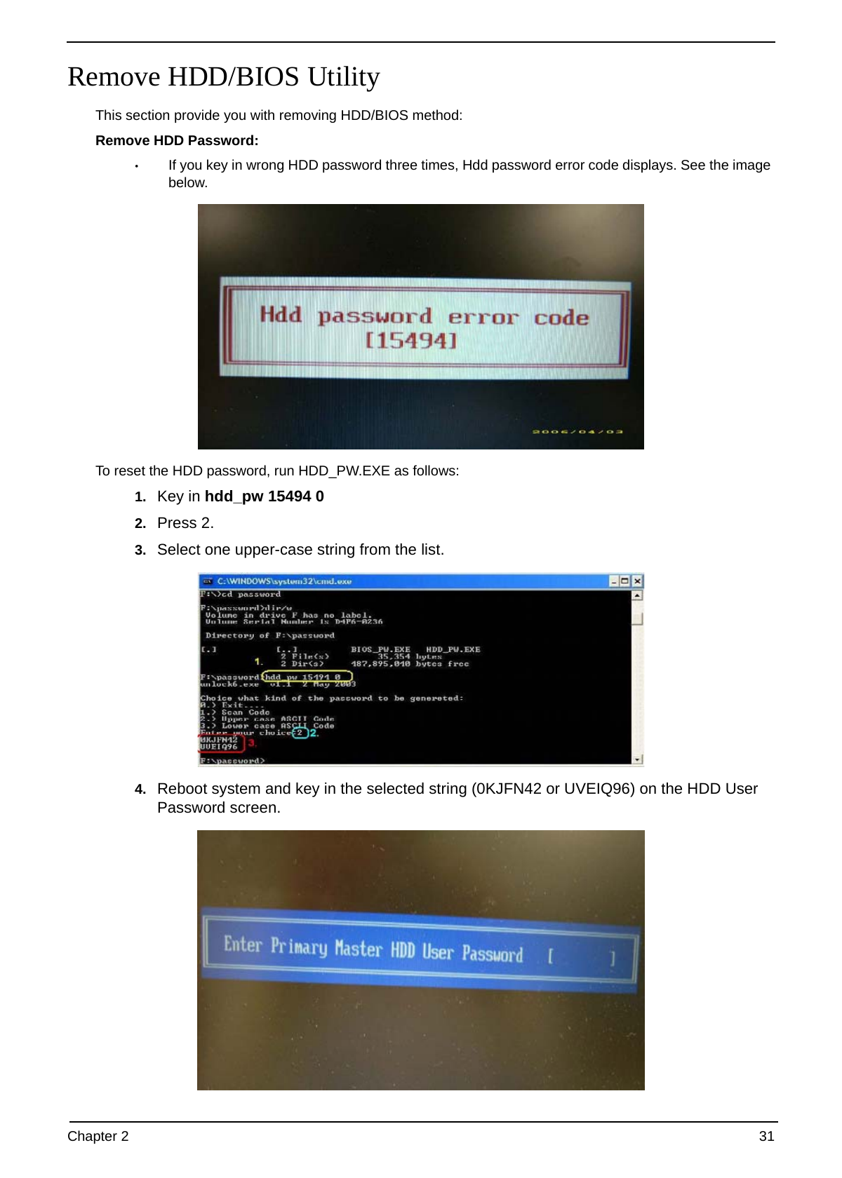
Remove HDD Password:
• If you key in wrong HDD password three times, Hdd password error code displays. See the image
below.
To reset the HDD password, run HDD_PW.EXE as follows:
1. Key in hdd_pw 15494 0
2. Press 2.
3. Select one upper-case string from the list.
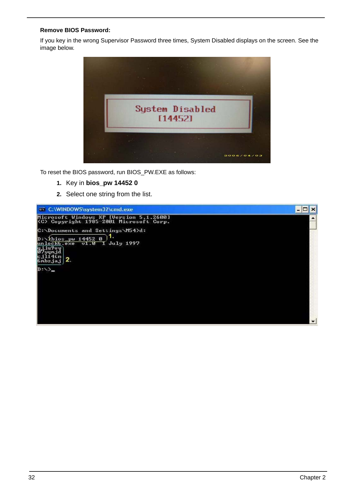
4. Reboot system and key in the selected string (0KJFN42 or UVEIQ96) on the HDD User
Password screen.
Chapter 2 31
Remove BIOS Password:
If you key in the wrong Supervisor Password three times, System Disabled displays on the screen. See the
image below.
To reset the BIOS password, run BIOS_PW.EXE as follows:
1. Key in bios_pw 14452 0
2. Select one string from the list.
32 Chapter 2
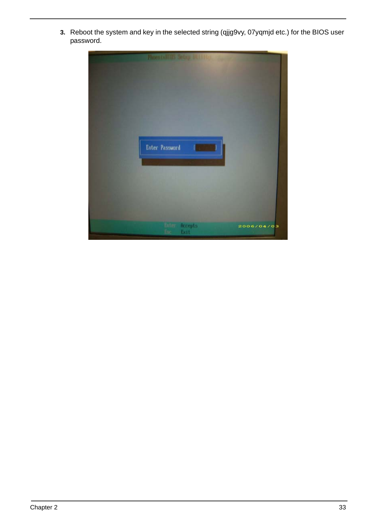
3. Reboot the system and key in the selected string (qjjg9vy, 07yqmjd etc.) for the BIOS user
password.
Chapter 2 33
34 Chapter 2
Chapter 3
Machine Disassembly and Replacement
This chapter contains step-by-step procedures on how to disassemble the notebook computer for
maintenance and troubleshooting.
Disassembly Requirements
To disassemble the computer, you need the following tools:
• Wrist grounding strap and conductive mat for preventing electrostatic discharge
• Flat screwdriver
• Philips screwdriver
• Plastic flat screwdriver
• Plastic tweezers
NOTE: The screws for the different components vary in size. During the disassembly process, group the
screws with the corresponding components to avoid mismatch when putting back the components.
Related Information
Please note that the images were taken using the HDD model, unless otherwise specified, and may differ
slightly from a SSD model.
The product previews seen in the disassembly procedures may not represent the final product color.
Chapter 3 35
General Information
Pre-disassembly Instructions
Before proceeding with the disassembly procedure, make sure that you do the following:
1. Turn off the power to the system and all peripherals.
2. Unplug the AC adapter and all power and signal cables from the system.
3. Place the system on a flat, stable surface.
4. Remove the battery pack.
Disassembly Process
The disassembly process is divided into the following sections:
• Upper cover disassembly
• LCD module disassembly
• Main unit disassembly
The flowcharts provided in the succeeding disassembly sections illustrate the entire disassembly sequence.
Observe the order of the sequence to avoid damage to any of the hardware components. For example, if you
want to remove the main board, you must first remove the keyboard, then disassemble the inside assembly
frame in that order.
Main Screw List
Screw Quantity Part Number
M2.5*8 (NL) 15 MA000005YG0
M2.5*5 (NL) 22 MA000007YG0
M2.5*3 (NL) 2 MA000005WG0
M2*3 (NL) 36 MA0000060G0
M2.5*4 (NL) 2 MA0000005G0
M2*6 (NL) 4 MMCK20060G0
M2*4-NI (NL) 5 MACK20040G0
M3*3 (NL) 4 MAAA03032G0
M2*6.5 4 MA0000096G0
M2.5*5.0 2 MA000002NG0
M2.5*6.5 4 MA000006C00
36 Chapter 3
External Module Disassembly Process
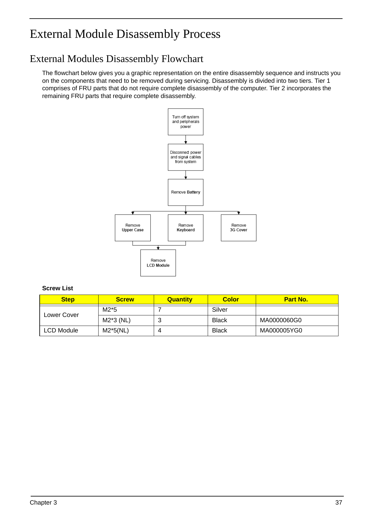
External Modules Disassembly Flowchart
The flowchart below gives you a graphic representation on the entire disassembly sequence and instructs you
on the components that need to be removed during servicing. Disassembly is divided into two tiers. Tier 1
comprises of FRU parts that do not require complete disassembly of the computer. Tier 2 incorporates the
remaining FRU parts that require complete disassembly.
Screw List
Step Screw Quantity Color Part No.
M2*5 7 Silver
Lower Cover
M2*3 (NL) 3 Black MA0000060G0
LCD Module M2*5(NL) 4 Black MA000005YG0
Chapter 3 37
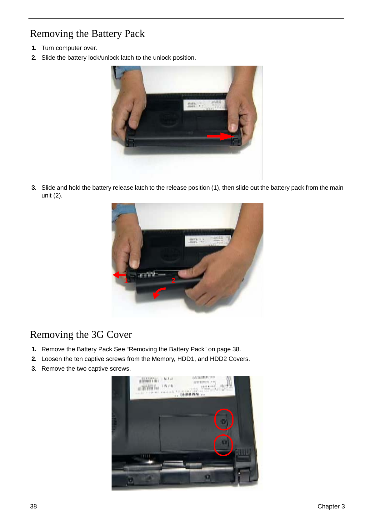
Removing the Battery Pack
1. Turn computer over.
2. Slide the battery lock/unlock latch to the unlock position.
3. Slide and hold the battery release latch to the release position (1), then slide out the battery pack from the main
unit (2).
1 2
Removing the 3G Cover
1. Remove the Battery Pack See “Removing the Battery Pack” on page 38.
2. Loosen the ten captive screws from the Memory, HDD1, and HDD2 Covers.
3. Remove the two captive screws.
38 Chapter 3
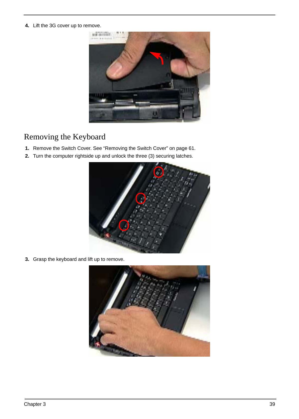
4. Lift the 3G cover up to remove.
Removing the Keyboard
1. Remove the Switch Cover. See “Removing the Switch Cover” on page 61.
2. Turn the computer rightside up and unlock the three (3) securing latches.
3. Grasp the keyboard and lift up to remove.
Chapter 3 39
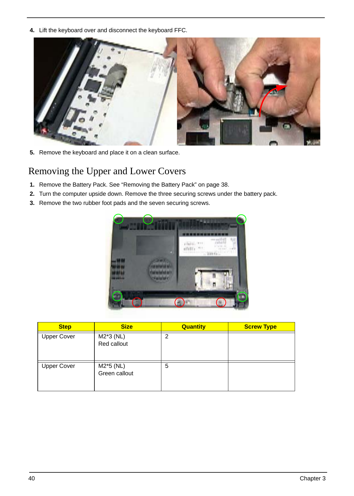
4. Lift the keyboard over and disconnect the keyboard FFC.
5. Remove the keyboard and place it on a clean surface.
Removing the Upper and Lower Covers
1. Remove the Battery Pack. See “Removing the Battery Pack” on page 38.
2. Turn the computer upside down. Remove the three securing screws under the battery pack.
3. Remove the two rubber foot pads and the seven securing screws.
Step Size Quantity Screw Type
Upper Cover M2*3 (NL) 2
Red callout
Upper Cover M2*5 (NL) 5
Green callout
40 Chapter 3
4. Disconnect the TouchPad FFC.
5. Turn the computer rightside up and remove the five (5) securing screws.
Step Size Quantity Screw Type
Upper Cover M2*5 (NL) 6
6. Grasp the bottom of the upper cover and pry apart.
Chapter 3 41
7. Lift the upper cover to remove completely.
42 Chapter 3
LCD Module Disassembly Process
LCD Module Disassembly Flowchart
Screw List
Step Screw Quantity Color Part No.
LCD Bezel M2.5*5 (NL) 4 Black MA000007YG0
Inverter Board M2.5*5 (NL) 1 Black MA000007YG0
Camera Module M2*3 (NL) 2 Black MA0000060G0
LCD Panel M2.5*5 (NL) 2 Black MA000007YG0
LCD Brackets M2*3 (NL) 8 Black MA0000060G0
Chapter 3 43
Removing the LCD Module
1. Remove the Upper Cover. See “Removing the Upper and Lower Covers” on page 40.
2. Disconnect the LCD cable from its connector
3. Disconnect and remove the antenna cables from the housing well.
NOTE: Main cable is black. The Auxiliary cable is white.
4. Remove the four securing screws from the hinges.
44 Chapter 3
Step Size Quantity Screw Type
LCD Module M2*5 (NL) 4
5. Tilt the LCD module so it sits at a 90 degree angle.
IMPORTANT:Ensure all cables are clear of the lower cover before removing the LCD module.
6. Grasp the module by both sides and lift upwards.
Removing the LCD Bezel
1. Remove the LCD Module. See “Removing the LCD Module” on page 44.
2. Remove the four round and the two semi-rectangular screw caps.
3. Remove the six (6) securing screws.
Step Size Quantity Screw Type
LCD Bezel M2*5 (NL) 6
Chapter 3 45
4. Starting from the inside edges, pry the inside of the bezel upwards from the panel. Continue moving left until
the bezel is removed. If necessary, use a plastic pry to release the corners of the bezel.
5. Lift up the bezel and remove it from the LCD Module.
Removing the Camera Board
1. Remove the LCD Bezel. See “Removing the LCD Bezel” on page 45.
2. Disconnect the Camera Module cable from its connector as shown.
3. Remove the camera board from the LCD cover.
46 Chapter 3
Removing the MIC Board
1. Remove the LCD Bezel. See “Removing the LCD Bezel” on page 45.
2. Disconnect the MIC cable from its connector as shown.
3. Remove the MIC board from the LCD cover.
Chapter 3 47
Removing the LCD Panel
1. Remove the LCD Bezel. See “Removing the LCD Bezel” on page 45.
2. Disconnect the MIC cable. See “Removing the MIC Board” on page 47.
3. Remove the five (5) securing screws from the LCD Module.
Step Size Quantity Screw Type
LCD Panel M2*4 (NL) 5
4. Grasp the left hinge and pivot down before pulling up.
5. Remove it from its housing well.
48 Chapter 3
6. Hold the LCD Panel from the sides and lift to remove. Place it on a clean surface.
Removing the LCD Brackets and FPC Cable
1. Remove the LCD Panel. See “Removing the LCD Panel” on page 48.
2. Turn the LCD panel over on a clean surface. Remove the adhesive strips securing the LCD cable.
3. Disconnect the LCD cable from its connector as shown.
Chapter 3 49
4. Remove the four securing screws from the LCD Panel brackets.
Step Size Quantity Screw Type
LCD Brackets M2*3 NL 4
50 Chapter 3
Main Unit Disassembly Process
Main Unit Disassembly Flowchart
Screw List
Step Screw Quantity Color Part No.
Speaker M2*3 (NL) 4 MA0000060G0
I/O Board M2.5*5 (NL) 1 MA000007YG0
Bluetooth Board M2*3 (NL) 1 MA0000060G0
Modem Module M2*3 (NL) 2 MA0000060G0
Mainboard M2.5*5 (NL) 1 MA000007YG0
Thermal Module M2*6.5 4 MA0000096G0
CPU Fan M2*4-NI (NL) 3 MACK20040G0
Chapter 3 51
Removing the WLAN Module
1. See “Removing the Battery Pack” on page 38.
2. Remove the HDD2 cover. See “Removing the 3G Cover” on page 38.
3. Remove the Turbo RAM. See “Removing the TV Tuner module” on page 53.
4. Disconnect the antenna cables from the WLAN board.
Step Size Quantity Screw Type
WLAN Module M2*3 (NL) 1
NOTE: The antenna cables were removed during the LCD module disassembly. See “Removing the LCD
Module” on page 44.
5. The module pops up. Remove it from the mainboard as shown.
52 Chapter 3
Removing the USB/LED/Power/Card Reader Board
1. Remove the upper cover. See “Removing the Upper and Lower Covers” on page 40.
2. Remove the three (3) securing screws as shown.
HDD SKU SSD SKU
Step Size Quantity Screw Type
HDD SKU: M2*3 (NL) 3
USB/LED/Power
board
SDD SKU: M2*3 (NL) 4
USB/LED/Power
board
3. Lift the board to expose the USB/LED/Power board to mainboard cable
Chapter 3 53
4. Lift the board to expose the USB/LED/Power board to mainboard cable.
5. Disconnect the cable and remove the board to a s
Removing the SSD Module
IMPORTANT:The SSD module is only available on the Aspire One SSD model.
1. Remove the mainboard. See “Removing the Mainboard” on page 56.
2. Disconnect the FFC from its connector.
54 Chapter 3
3. Disconnect the FFC cable from the module.
NOTE: To prevent damage to device, avoid pressing down on it or placing heavy objects on top of it.
4. Remove the two securing screws.
Step Size Quantity Screw Type
SSD Module M2*3 (NL) 2
5. Remove the SSD module.
Chapter 3 55
Removing the Mainboard
1. Remove the Upper Cover. See “Removing the Upper Cover” on page 67.
2. Remove the WLAN module. See “Removing the WLAN Module” on page 52.
3. Remove the USB/LED/Power/Card Reader Board. See “Removing the USB/LED/Power/Card Reader Board”
on page 53.
4. Disconnect the speaker to mainboard cable.
5. Remove the single securing screw.
Step Size Quantity Screw Type
WLAN Module M2*3 (NL) 1
56 Chapter 3
6. Grip the mainboard and remove.
NOTE: The SSD image may differ from the following illustration.
Step Size Quantity Screw Type
Mainboard M2.5*6.5 (NL) 1
Removing the Speaker Module
1. Remove the Upper Cover. See “Removing the Upper Cover” on page 67.
2. Peel back the two adhesive strips.
Chapter 3 57
3. Remove the four (4) securing screws (2 on each side).
Step Size Quantity Screw Type
Speaker Module M2*3 (NL) 4
4. Remove the Speaker Module from the upper cover.
Removing the Hard Disk Drive Module
IMPORTANT:The HDD is only available on the Aspire One HDD model.
1. Remove the mainboard. See “Removing the Mainboard” on page 56.
2. Remove the two securing screws to release the carrier.
58 Chapter 3
Step Size Quantity Screw Type
HDD Module M2.5*4 (NL) 2
3. Hold the carrier and slide the HDD away from the mainboard.
NOTE: To prevent damage to device, avoid pressing down on it or placing heavy objects on top of it.
4. Remove the four screws (two each side) securing the HDD to the carrier.
Chapter 3 59
Step Size Quantity Screw Type
HDD Carrier M3*3.5 (NL) 4
5. Turn the HDD on its side and pull the carrier away.
Removing the DIMM Module
IMPORTANT:The Aspire One SSD model does not come standard with DIMM modules. The modules are
optional components for this model.
1. Remove the mainboard. See “Removing the Mainboard” on page 56.
2. Push out the release latches on both sides of the DIMM socket to release the DIMM module.
60 Chapter 3
3. Remove the DIMM module.
Removing the Thermal Module
1. Remove the Mainboard. See “Removing the Mainboard” on page 56.
2. Turn the Mainboard CPU side up, and place it on a clean surface.
3. Grip the cable connector and disconnect the Fan cable from the mainboard.
IMPORTANT:Do not grip the cable itself to prevent stripping.
Chapter 3 61
4. Remove the three securing screws from the heatsink.
Step Size Quantity Screw Type
Mainboard M2*3(NL) 3
5. Remove the thermal module.
62 Chapter 3
LCD Module Reassembly Procedure
Replacing the LCD Brackets and FPC Cable
1. Replace the four LCD brackets as shown.
IMPORTANT:The indicator pairs on the brackets must be located diagonally opposite each other.
2. Turn the LCD panel over and connect the FPC cable to the panel.
3. Secure the cable with the adhesive strips as shown.
Chapter 3 63
Replacing the LCD Panel
IMPORTANT:Before installing, take care of the following items:
q All cabling must be tucked tightly and close to the panel
q Check that the cables are tucked under the hinge brackets and run on the outside of the hinges
1. Place the LCD Panel in to the case as shown. 2. Replace the left hinge as shown.
3. Replace the five securing screws as shown.
64 Chapter 3
Replacing the Mic Board
1. Replace the Mic board in to the case. 2. Connect the MIC cable as shown.
Replacing the Camera Board
1. Replace the camera board in to the case. 2. Connect the camera cable as shown.
Chapter 3 65
Replacing the LCD Bezel
1. Starting from the bottom, locate the bezel correctly and press down the edges until there are no gaps
between the bezel and the LCD Module.
2. Replace the six screws and the rubber screw caps provided.
66 Chapter 3
Main Module Reassembly Procedure
Replacing the Thermal Module
1. Replace the Fan module on the Mainboard. 2. Replace the three screws in the order shown,
starting with number 1.
3. Connect the Fan cable to the Mainboard.
Replacing the DIMM Module
IMPORTANT:The Aspire One SSD model does not come standard with DIMM modules. The modules are
optional components.
1. Insert DIMM1 in to the socket. 2. Press down to locate DIMM correctly.
Chapter 3 67
Replacing the Hard Disk Drive Module
IMPORTANT:The HDD is only available on the Aspire One HDD computer model.
1. Place the HDD in the HDD carrier. 2. Replace the four screws (two each side) to secure
the carrier.
3. Hold the carrier and slide the HDD toward the 4. Replace the two securing screws.
mainboard until the interface connects.
Replacing the Speaker Module
1. Replace the Speaker Module in the lower cover. 2. Replace the four securing screws.
68 Chapter 3
3. Replace the two adhesive strips.
Chapter 3 69
Replacing the Mainboard
IMPORTANT:Before replacing the motherboard, take care of the following items:
q Check that LED isn`t broken (top of mainboard)
q Check that the mylar next to the CPU module isn`t damaged (bottom of mainboard)
q Check the thermal power supply cable is connected properly
1. Insert the mainboard left side first into the lower 2. Replace the securing screw on the Mainboard.
cover.
3. Connect the speaker cable to the mainboard.
70 Chapter 3
Replacing the SDD Module
IMPORTANT:The SSD module is only available on the Aspire One SSD computer model.
1. Place the SDD in the lower case. 2. Replace the two screws to secure the module.
3. Connect the FFC cable to the module and close 4. Connect the FFC cable to the mainboard and close
the cable latch. the cable latch.
Chapter 3 71
Replacing the USB/LED/Power/Card Reader Board
IMPORTANT:Before installing the USB board, take care of the following items:
q Check that LED isn`t broken
q SLIDER work smoothly
1. Connect the cable to the board. 2. Turn the board over and place it in the lower case.
3. Replace the three or four screws (depending on SKU) to secure the module.
HDD SKU SSD SKU
4. Connect the FFC cable to the module and close 5. Connect the FFC cable to the mainboard and close
the cable latch. the cable latch.
72 Chapter 3
Replacing the WLAN Board
1. Insert the WLAN board in to the socket. 2. Push the board down and replace the securing
screw.
Replacing the LCM Module
1. Place the LCM module on to the lower cover at a 90 degree angle.
IMPORTANT:Ensure all cables are clear of the hinges before replacing the LCM module.
2. Replace the four screws (two each side) to secure the LCM module to the lower cover.
Chapter 3 73
3. Replace the antenna cables in the housing well, as shown.
4. Replace the two antenna cables. 5. Connect the LCD cable to the mainboard.
NOTE: The following is the correct cable-color to
connector designation: Black to MAIN (left)
and White to AUX (right).
74 Chapter 3
Replacing the Upper Cover
IMPORTANT:While replacing the upper cover, take note of the following items:
q Check that the mainboard is tucked underneath the housing wells in the lower cover
q Check that the speaker cable is attached
q Check that the antenna cables are tucked inside the housing well and do not interfere with the card reader
q Antenna cables must be secured to the chassis walls with the provided gasket tape
q Antenna cable on the right side must pass through the right side of hinge block
q Make sure that the 40-PIN Cable doesn`t interfere with the speaker module
1. Place the upper cover over the lower base, hinge 2. Set the Upper Cover down on the lower base and
side first. press down as shown.
3. Replace the six securing screws on the Upper 4. Reconnect the touchpad FCC cable and close the
Cover. cable latch.
Chapter 3 75
5. Turn the computer upside down and replace the eight securing screws on the bottom panel to attach the
upper and lower covers.
6. Replace the two rubber foot pads.
Replacing the Keyboard
1. Replace keyboard cable to the mainboard, and 2. Turn the keyboard over and place the front edge
secure the locking latch. first in the mounting.
3. Press down on the areas shown below to secure in place.
76 Chapter 3
Replacing the 3G cover
1. Replace the 3G cover. 2. Secure the two captive screws.
Replacing the Battery
1. Slide and hold the battery release latch (1), insert 2. Slide the battery lock/unlock latch to the lock
battery in to the main unit (2). position.
1 2
Chapter 3 77
78 Chapter 3
Chapter 4
Troubleshooting
Common Problems
Use the following procedure as a guide for computer problems.
NOTE: The diagnostic tests are intended to test only Acer products. Non-Acer products, prototype cards, or
modified options can give false errors and invalid system responses.
1. Obtain the failing symptoms in as much detail as possible.
2. Verify the symptoms by attempting to re-create the failure by running the diagnostic test or by repeating
the same operation.
3. Use the following table with the verified symptom to determine which page to go to.
Symptoms (Verified) Go To
Power On Issue Page 80
No Display Issue Page 81
LCD Failure Page 84
Internal Keyboard Failure Page 84
TouchPad Failure Page 85
Internal Speaker Failure Page 85
Internal Microphone Failure Page 87
Rightside USB Failure Page 89
Power Button Failure Page 89
Other Functions Failure Page 90
Intermittent Failures Page 91
Undermined Failures Page 91
4. If the Issue is still not resolved, see “Online Support Information” on page 155.
Chapter 4 79
Power On Issue
If the system doesn’t power on, perform the following actions one at a time to correct the problem. Do not
replace a non-defective FRUs:
Computer Shutsdown Intermittently
If the system powers off at intervals, perform the following actions one at a time to correct the problem.
1. Check the power cable is properly connected to the computer and the electrical outlet.
2. Remove any extension cables between the computer and the outlet.
3. Remove any surge protectors between the computer and the electrical outlet. Plug the computer directly
into a known good electrical outlet.
4. Remove all external and non-essential hardware connected to the computer that are not necessary to
boot the computer to the failure point.
5. Remove any recently installed software.
6. If the Issue is still not resolved, see “Online Support Information” on page 155.
80 Chapter 4
No Display Issue
If the Display doesn’t work, perform the following actions one at a time to correct the problem. Do not replace
a non-defective FRUs:
Chapter 4 81
No POST or Video
If the POST or video doesn’t display, perform the following actions one at a time to correct the problem.
1. Make sure that the internal display is selected. On this notebook model, switching between the internal
display and the external display is done by pressing Fn+F5. Reference Product pages for specific model
procedures.
2. Make sure the computer has power by checking at least one of the following occurs:
• Fans start up
• Status LEDs light up
If there is no power, see “Power On Issue” on page 80.
3. Drain any stored power by removing the power cable and battery and holding down the power button for
10 seconds. Reconnect the power and reboot the computer.
4. Connect an external monitor to the computer and switch between the internal display and the external
display is by pressing Fn+F5 (on this model).
If the POST or video appears on the external display, see “LCD Failure” on page 84.
5. Disconnect power and all external devices including port replicators or docking stations. Remove any
memory cards and CD/DVD discs. Restart the computer.
If the computer boots correctly, add the devices one by one until the failure point is discovered.
6. Reseat the memory modules.
7. Remove the drives (see “Disassembly Process” on page 36).
8. If the Issue is still not resolved, see “Online Support Information” on page 155.
82 Chapter 4
Abnormal Video Display
If video displays abnormally, perform the following actions one at a time to correct the problem.
1. Reboot the computer.
2. If permanent vertical/horizontal lines or dark spots display in the same location, the LCD is faulty and
should be replaced. See “Disassembly Process” on page 36.
3. If extensive pixel damage is present (different colored spots in the same locations on the screen), the LCD
is faulty and should be replaced. See “Disassembly Process” on page 36.
4. Adjust the brightness to its highest level. See the User Manual for instructions on adjusting settings.
NOTE: Ensure that the computer is not running on battery alone as this may reduce display brightness.
If the display is too dim at the highest brightness setting, the LCD is faulty and should be replaced. See
“Disassembly Process” on page 36.
5. Check the display resolution is correctly configured:
a. Minimize or close all Windows.
b. If display size is only abnormal in an application, check the view settings and control/mouse wheel
zoom feature in the application.
c. If desktop display resolution is not normal, right-click on the desktop and select
Personalize´ Display Settings.
d. Click and drag the Resolution slider to the desired resolution.
e. Click Apply and check the display. Readjust if necessary.
6. Roll back the video driver to the previous version if updated.
7. Remove and reinstall the video driver.
8. Check the Device Manager to determine that:
• The device is properly installed. There are no red Xs or yellow exclamation marks.
• There are no device conflicts.
• No hardware is listed under Other Devices.
9. If the Issue is still not resolved, see “Online Support Information” on page 155.
10. Run the Windows Memory Diagnostic from the operating system DVD and follow the onscreen prompts.
11. If the Issue is still not resolved, see “Online Support Information” on page 155.
Random Loss of BIOS Settings
If the computer is experiencing intermittent loss of BIOS information, perform the following actions one at a
time to correct the problem.
1. If the computer is more than one year old, replace the CMOS battery.
2. Run a complete virus scan using up-to-date software to ensure the computer is virus free.
3. If the computer is experiencing HDD or ODD BIOS information loss, disconnect and reconnect the power
and data cables between devices.
If the BIOS settings are still lost, replace the cables.
4. If HDD information is missing from the BIOS, the drive may be defective and should be replaced.
5. Replace the Motherboard.
6. If the Issue is still not resolved, see “Online Support Information” on page 155.
Chapter 4 83
LCD Failure
If the LCD fails, perform the following actions one at a time to correct the problem. Do not replace a non-
defective FRUs:
Built-In Keyboard Failure
If the built-in Keyboard fails, perform the following actions one at a time to correct the problem. Do not replace
a non-defective FRUs:
84 Chapter 4
TouchPad Failure
If the TouchPad doesn’t work, perform the following actions one at a time to correct the problem. Do not
replace a non-defective FRUs:
Internal Speaker Failure
If the internal Speakers fail, perform the following actions one at a time to correct the problem. Do not replace
a non-defective FRUs:
Sound Problems
If sound problems are experienced, perform the following actions one at a time to correct the problem.
1. Reboot the computer.
2. Navigate to Start´ Control Panel´ System and Maintenance´ System´ Device Manager. Check
the Device Manager to determine that:
Chapter 4 85
• The device is properly installed.
• There are no red Xs or yellow exclamation marks.
• There are no device conflicts.
• No hardware is listed under Other Devices.
3. Roll back the audio driver to the previous version, if updated recently.
4. Remove and reinstall the audio driver.
5. Ensure that all volume controls are set mid range:
a. Click the volume icon on the taskbar and drag the slider to 50. Ensure that the volume is not muted.
b. Click Mixer to verify that other audio applications are set to 50 and not muted.
6. Navigate to Start´ Control Panel´ Hardware and Sound´ Sound. Ensure that Speakers are selected
as the default audio device (green check mark).
NOTE: If Speakers does not show, right-click on the Playback tab and select Show Disabled Devices
(clear by default).
7. Select Speakers and click Configure to start Speaker Setup. Follow the onscreen prompts to configure
the speakers.
8. Remove and recently installed hardware or software.
9. Restore system and file settings from a known good date using System Restore.
If the issue is not fixed, repeat the preceding steps and select an earlier time and date.
10. Reinstall the Operating System.
11. If the Issue is still not resolved, see “Online Support Information” on page 155.
86 Chapter 4
Internal Microphone Failure
If the internal Microphone fails, perform the following actions one at a time to correct the problem. Do not
replace a non-defective FRUs:
Microphone Problems
If internal or external Microphones do no operate correctly, perform the following actions one at a time to
correct the problem.
1. Check that the microphone is enabled. Navigate to Start´ Control Panel´ Hardware and Sound´
Sound and select the Recording tab.
2. Right-click on the Recording tab and select Show Disabled Devices (clear by default).
3. The microphone appears on the Recording tab.
4. Right-click on the microphone and select Enable.
5. Select the microphone then click Properties. Select the Levels tab.
6. Increase the volume to the maximum setting and click OK.
7. Test the microphone hardware:
a. Select the microphone and click Configure.
b. Select Set up microphone.
c. Select the microphone type from the list and click Next.
d. Follow the onscreen prompts to complete the test.
8. If the Issue is still not resolved, see “Online Support Information” on page 155.
Chapter 4 87
HDD Not Operating Correctly
If the HDD does not operate correctly, perform the following actions one at a time to correct the problem.
1. Disconnect all external devices.
2. Run a complete virus scan using up-to-date software to ensure the computer is virus free.
3. Run the Windows Vista Startup Repair Utility:
a. insert the Windows Vista Operating System DVD in the ODD and restart the computer.
b. When prompted, press any key to start to the operating system DVD.
c. The Install Windows screen displays. Click Next.
d. Select Repair your computer.
e. The System Recovery Options screen displays. Click Next.
f. Select the appropriate operating system, and click Next.
NOTE: Click Load Drivers if controller drives are required.
g. Select Startup Repair.
h. Startup Repair attempts to locate and resolve issues with the computer.
i. When complete, click Finish.
If an issue is discovered, follow the onscreen information to resolve the problem.
4. Run the Windows Memory Diagnostic Tool. For more information see Windows Help and Support.
5. Restart the computer and press F2 to enter the BIOS Utility. Check the BIOS settings are correct and that
CD/DVD drive is set as the first boot device on the Boot menu.
6. Ensure all cables and jumpers on the HDD and ODD are set correctly.
7. Remove any recently added hardware and associated software.
8. Run the Windows Disk Defragmenter. For more information see Windows Help and Support.
9. Run Windows Check Disk by entering chkdsk /r from a command prompt. For more information see
Windows Help and Support.
10. Restore system and file settings from a known good date using System Restore.
If the issue is not fixed, repeat the preceding steps and select an earlier time and date.
11. Replace the HDD. See “Disassembly Process” on page 36.
88 Chapter 4
USB Failure (Rightside)
If the rightside USB port fails, perform the following actions one at a time to correct the problem. Do not
replace a non-defective FRUs:
Power Button Failure
If the Power Button fails, perform the following actions one at a time to correct the problem. Do not replace a
non-defective FRUs:
Chapter 4 89
External Mouse Failure
If an external Mouse fails, perform the following actions one at a time to correct the problem.
1. Try an alternative mouse.
2. If the mouse uses a wireless connection, insert new batteries and confirm there is a good connection. See
the mouse user manual.
3. If the mouse uses a USB connection, try an alternate USB port.
4. Try an alternative program to verify mouse operation. Reinstall the program experiencing mouse failure.
5. Restart the computer.
6. Remove any recently added hardware and associated software.
7. Remove any recently added software and reboot.
8. Restore system and file settings from a known good date using System Restore.
If the issue is not fixed, repeat the preceding steps and select an earlier time and date.
9. Run the Event Viewer to check the events log for errors. For more information see Windows Help and
Support.
10. Roll back the mouse driver to the previous version if updated recently.
11. Remove and reinstall the mouse driver.
12. Check the Device Manager to determine that:
• The device is properly installed. There are no red Xs or yellow exclamation marks.
• There are no device conflicts.
• No hardware is listed under Other Devices.
13. If the Issue is still not resolved, see “Online Support Information” on page 155.
Other Failures
If the CRT Switch, Dock, LAN Port, external MIC or Speakers, PCI Express Card, 5-in-1 Card Reader or
Volume Wheel fail, perform the following general steps to correct the problem. Do not replace a non-defective
FRUs:
1. Check Drive whether is OK.
2. Check Test Fixture is ok.
3. Swap M/B to Try.
90 Chapter 4
Intermittent Problems
Intermittent system hang problems can be caused by a variety of reasons that have nothing to do with a
hardware defect, such as: cosmic radiation, electrostatic discharge, or software errors. FRU replacement
should be considered only when a recurring problem exists.
When analyzing an intermittent problem, do the following:
1. Run the advanced diagnostic test for the system board in loop mode at least 10 times.
2. If no error is detected, do not replace any FRU.
3. If any error is detected, replace the FRU. Rerun the test to verify that there are no more errors.
Undetermined Problems
The diagnostic problems does not identify which adapter or device failed, which installed devices are incorrect,
whether a short circuit is suspected, or whether the system is inoperative.
Follow these procedures to isolate the failing FRU (do not isolate non-defective FRU).
NOTE: Verify that all attached devices are supported by the computer.
NOTE: Verify that the power supply being used at the time of the failure is operating correctly. (See “Power On
Issue” on page 80.):
1. Power-off the computer.
2. Visually check them for damage. If any problems are found, replace the FRU.
3. Remove or disconnect all of the following devices:
• Non-Acer devices
• Printer, mouse, and other external devices
• Battery pack
• Hard disk drive
• DIMM
• CD-ROM/Diskette drive Module
• PC Cards
4. Power-on the computer.
5. Determine if the problem has changed.
6. If the problem does not recur, reconnect the removed devices one at a time until you find the failing FRU.
7. If the problem remains, replace the following FRU one at a time. Do not replace a non-defective FRU:
• System board
• LCD assembly
Chapter 4 91
Frequently Asked Questions (FAQ)
This section provides help in the form of questions and answers for commonly encountered troubleshooting
issues.
If the system encountered problem, where can I get assistance?
When you encountered any problem, we recommend you take the following steps to handle:
1. Please read the Quick Guide
• When you encountered usage problem, we strongly recommend you to read the attached Quick Guide for
reference. See “How to browse the Aspire One Quick Guide?” on page 94.
2. Reference Linpus FAQ webpage
• Linpus FAQ webpage (http://www.linpus.com/xampp/modules/smartfaq/) will periodically update the FAQ
from the user and community; user may visit the web site to search for the question.
3. Email Linpus Helpdesk Support
• You can write your email to helpdesk@linpus.com, we have dedicated people to serve you.
Which peripheral equipment supports by Acer Aspire One?
Not only the system built-in peripheral devices have fully support, Acer Aspire One also provides the full
support of USB interface devices such as USB drive, external CD/DVD-ROM, external Hard drive and so on.
Also, the built-in multi card-reader can support SD/MMS/MS-PRO/xD those most common memory card. In
future, user may use the Live-update to upgrade the system to support the SDHC/SD2.0 too.
I want to expand the memory and storage device of Acer Aspire One, how can I do so?
Acer Aspire One allows the user to expand the memory via the expansion slot at the machine bottom. Please
refer to the system specification handbook to obtain the related information of the memory model. For the
internal storage device, Acer Aspire One does not provide the expansion ability.
Can Acer Aspire One handle my original file stored in Windows format?
Acer Aspire One has the corresponding applications to handle almost all the file formats under windows
environment. For example, for the normal file formats such as .doc, .xls, .ppt, user can use OpenOffice.org to
edit and store. Also, for graphic, audio, video, email and others, Acer Aspire One do provide some applications
for processing. The following is the applications mapping table:
Windows Application / File Linux Alternative Solution
Word OpenOffice Writer 2.3
Excel OpenOffice Impress 2.3
PowerPoint OpenOffice Presentation 2.3
Image processing applications KolourPaint, Photo Master
Acrobat Reader Acrobat Reader for Linux 8.1.2
MP3 and other audio files Media Master
Internet Explorer Firefox 2.0.0.14
Videos Media Master
Audio CD Playback Media Master
MSN/ICQ/QQ Acer Aspire One Messenger 1.01.2012
92 Chapter 4
Can the Messenger of Acer Aspire One connect to MSN, Yahoo Messenger, Google
Talk and other live communication tools?
Yes. The Messenger of Acer Aspire One can allow the user to login MSN, Yahoo Messenger, Google Talk, AIM
and so on.
I want to preserve Messenger Communication record, how can I do so?
Please open the Messenger Communication software of Aspire One, at the menu bar, select the Tools and
then select Messages. Just check the option Automatically keep a history of each conversation.
How Acer Aspire One performs System Recovery?
Each Acer Aspire One is bundled with a system recovery CD during shipping. At any time, user can select any
time to restore the machine to the initial factory setting. User just need to configure the system (start by CD-
ROM) and place the system recovery CD to the CD/DVD-ROM, during system startup, just follow the
instruction to recovery the system.
Does other Linux applications capable to run at Acer Aspire One?
Basically, the answer is YES. However, we strongly recommend that normal user to use the Live Update to
download those ACER certified package.
Which language does Acer Aspire One supports?
Acer Aspire One system is using Unicode. According to the user selection, user can set to display English,
Japanese, German, French, Italian, Spanish, Portugal, Dutch, Brazil, Russian, Arabic, Turkish, Vietnamese,
Thailand and so on.
During the installation, user just simply selects the desired language and the system will go ahead to install
that selected language of Operating System.
How many input methods the Linpus Linux Lite provide?
Other than English, Japanese, German, French, Italian, Spanish, Portugal, Dutch, Brazil, Russian, Linpus
Linux Lite also provides several input modes for Traditional and Simplified Chinese (ex: ZhuYin, Cangjie,
Array30, EZ-Big, Wubi, etc...). However, only Traditional and Simplified Chinese version of Linpus Linux Lite
supports this function.
Chapter 4 93
How can I remove non-necessary input methods?
We only support such function for the Traditional and Simplified Chinese version of Linpus Linux Lite.
How may I add more selection of input method?
We only support such function for the Traditional and Simplified Chinese version of Linpus Linux Lite.
How to select or switch the input mode at your keyboard?
We only support such function for the Traditional and Simplified Chinese version of Linpus Linux Lite.
May we setup Hotkeys by ourselves?
We only support such function for the Traditional and Simplified Chinese version of Linpus Linux Lite.
What is the Kernel version for Linpus Linux Lite?
The current version is 2.6.23.9lw and user is able to update the kernel via the Online-update function.
How can we adjust the monitor DPI (dots per inch)?
Currently, Linpus Linux Lite does not support such function. See “Where can I view my System Hardware
Summary?” on page 95.
My Monitor Icons look too small/large, may I reset it?
Currently, Linpus Linux Lite does not support such function.
May I set up different background picture and/or background color?
Currently, Linpus Linux Lite does not support such function.
May I add/delete UI icons, adjust UI position, or change UI name?
Currently, Linpus Linux Lite does not support such function.
Can I adjust System Power Management?
At the lower right corner of the desktop Taskbar, there is an icon KPowersave. Right click on that icon, a
window pop-up and select Setting CPU Frequency Method.
User has 3 options:
Performance´ CPU always runs at the higher speed
Dynamic´ CPU speed depend on the user action
Balance´ CPU always runs at the lower speed
How to browse the Aspire One Quick Guide?
Double click on Help, user can then browse Aspire One Quick Guide.
94 Chapter 4
How can I fast back to Home Page?
At the lower left corn of the Desktop Taskbar, there is a Home icon. When you click the icon, all the running
windows will minimize and Home Page will show up.
Where can I view my System Hardware Summary?
Press the combination key Fn+F2 to display the System Information click on the tab System Summary to
view the system hardware information.
Chapter 4 95
Where can I view my Multimedia Hardware Information?
Press the combination key Fn+F2 to display the System Information click on the tab Multimedia to view the
multimedia information.
96 Chapter 4
Where can I see my Network Hardware Information?
Press the combination key Fn+F2 to display the System Information click on the tab Network to view the
network hardware information.
How can I read the date from USB drive and CD/DVD-ROM?
Just plug in the USB drive or put in the CD to CD/DVD-Rom, Linpus Linux Lite will automatically detect and
mount. At the same time, a corresponding icon will show up at My File under the tab File. When user clicks on
the device, he/she can access and work on the file or application.
Green Icon
If user needs to unmount the device, just right click on the green icon, a popup window show up and select
Unmount volume.
Chapter 4 97
What is the Wireless Network Security Protocol supported by Linpus Linux Lite?
Linpus Linux Lite support the following security protocols:
• WEP 128 bit key
• WEP 40/104 Bit HEX
• WEP 40/128 Bit ASCII
• WPA & WPA2 Personal
User just need to click on the network manager icon and select the desired wireless point. The network
manager will automatically detect the security protocol and user just need to type the password.
How to setup the Network Printer?
Take the Windows network as the example, please first select Setting and then Printer, just presses New
Printer at the Toolbar. Set the Selected Connection as Windows Printer via SAMBA; click on the desired
SMB print at Shared, select the wanted printer and go Forward. Select the printer’s manufacturer and the
model, go on the next page to setup the printer name. Press the Apply button when go on the next page.
98 Chapter 4
Why I can not use my Network Printer?
Before installation of the network printer, user must confirm whether to satisfy the following condition:
• Does the network device activate or not?
• Does your system really connect to local area network (LAN)?
• Does your system install “samba” and activate the service?
When user uses SMB common printer of Windows 95/98/NT, user must pay attention to the Authentication.
Regarding to Windows 95/98, you could set the security setting as Sharing Level to avoid any problem of
such issue.
But regarding Windows NT, user can not use this way to avoid. At this time, user needs to establish the Linux
user's account number and the password in Window NT, and guarantees this user's NT account and the
password must be consistent with the corresponding Linux account and the password.
Otherwise user will be unable to log in the remote machine, to some extent, not even using the printer on the
remote machine too.
How to share the local printer to other printer?
First, please enter the printer settings, then choose the printer which we want to share. And enable the state
Shared, now you can share the local printer to other computers.
Chapter 4 99
How to online update applications?
Please enter Settings page, and press Live Update then enter online update page, and press Update. It will
connect to the live update server automatically, and it will list the applications that can be update, please press
Install, system will download and install the applications.
How can I adjust Date/Time/Timezone?
Please enter Settings page, and press Date/Time it will shows the setting menu, then you can adjust time,
date, and time zone.
100 Chapter 4
Where can I see my system’s performance?
Please press Ctrl+Alt+Del and it will shows the System Monitor. Then press Resources, now you can see
your system's status.
Where can I see my system’s peripheral devices?
Please press Ctrl+Alt+Del and it will shows the System Monitor. Then press File Systems, now you can see
your system's devices.
Chapter 4 101
Where can I see the running processes in my system?
Please press Ctrl+Alt+Del, and it will shows the System Monitor. Then press Processes now you can see
the running process's status.
How can I set the screensaver?
In this version, we do not open such permission to user.
How can I reset the password?
Please enter Settings page, and press User & Password. The setting menu will display and please press
Change Password. Now, you can then change your password.
After using OpenOffice.org, how is my old files with MS Office format? Should all the
file doing again? Is there any conversion utility?
Actually, OpenOffice.org can read the file with MS Office format, therefore the old files need not doing again. In
case of having a complex page layout or macro existed in your document, then you can consider to do it again
under OpenOffice.org. In fact, for the old files format issue, OpenOffice.org did well than Microsoft, for
example, Office XP is not able to read Office 95 files.
However, OpenOffice.org not only read MS Office 95/97/2000/XP, but also save the file as MS Office the 95/
97/2000/XP format.
In addition, OpenOffice.org provides file conversion wizard, which is able to convert original MS Office file
format to OpenOffice.org format.
102 Chapter 4
How to install and start the Webcam?
Please click and select Webcam in the paging of Fun, the system will be detected and examined to this
hardware equipment automatically. Please operate and establish in accordance with the instruction on its
picture while using.
How should I move and copy the file?
Move (user to only need it to File Manager first, in dilatory way, the file moving wanting is moved to the goal
area. Copy (click and select the file wanted to duplicate, choose the tool to list Edit´ Copy or press the right
key to choose to be Copy to the file wanting to copy, move and choose the tool to list Edit to the goal area ´
Paste, or press the right key to choose to be Paste to the goal area.
How to shut-down?
So long as click and select to operate the graphic presentation below the picture right (the following picture
show), after pushing shut-down and selecting, can close the system.
How to transfer IE bookmark to Firefox?
Select File´ Import of the function menu of Firefox, then click Internet Explorer after selection show on the
page you want to transfer. This way you will be able to IE on the my favorite (bookmark), by the memory of
the password, and the option to set your browser to transfer records in Firefox.
How to use webpages that store or made before in Firefox?
You can open or tow .html or .htm file to Firefox directly. Or you can The window which puts to Firefox can be
opened automatically to tow .html or .htm file directly. Or use the function of open document to open.
There are some Flash webpages, unable to show normally in my Firefox?
You can download the newest Flash Player Installers for Linux in Adobe Lab (http://labs.adobe.com/)
How to browser PDF file?
The system has already built Adobe Reader 8, it only needed to click to carry out the file had a look around
directly.
Is there any virus scanner for linux?
At present, about 99.xx% virus all aims at attacking the Windows system, under Linux environment, it cannot
be influential, currently the so-called anti-virus for Linux, is mostly coordinates with the Mail system, which also
is the Windows virus. Thus, seven if the Linux directly open the email, the system does not any infection but
user must pay attention to the RootKit and other back door program (for Linux).
Webpage garbled?
The character encoding may be unable to automatically detect.
Recommendations available [view] / character encoding and then choose the appropriate coding language.
Chapter 4 103
How to search the file?
Type the file name to look for on desk-top upper right corner Search Bar.
Choosing Local, then you can search by selecting the magnifying glass.
104 Chapter 4
POST Code Reference Tables
These tables describe the POST codes and components of the POST process.
Sec:
NO_EVICTION_MODE_DEBUG EQU 1 (CommonPlatform\sec\Ia32\SecCore.inc)
Code Component
0xC2 MTRR setup
0xC3 Enable cache
0xC4 Establish cache tags
0xC5 Enter NEM, Place the BSP in No Fill mode, set CR0.CD = 1, CR0.NW = 0.
0xCF Cache Init Finished
Memory:
DEBUG_BIOS EQU 1 (Chipset\Alviso\MemoryInitAsm\IA32\IMEMORY.INC)
Code Component
0xA0 First memory check point
0x01 Enable MCHBAR
0x02 Check for DRAM initialization interrupt and reset fail
0x03 Verify all DIMMs are DDR or DDR2 and unbuffered
0x04 Detect an improper warm reset and handle
0x05 Detect if ECC SO-DIMMs are present in the system
0x06 Verify all DIMMs are single or double sided and not asymmetric
0x07 Verify all DIMMs are x8 or x16 width
0x08 Find a common CAS latency between the DIMMS and the MCH
0x09 Determine the memory frequency and CAS latency to program
0x10 Determine the smallest common TRAS for all DIMMs
0x11 Determine the smallest common TRP for all DIMMs
0x12 Determine the smallest common TRCD for all DIMMs
0x13 Determine the smallest refresh period for all DIMMs
0x14 Verify burst length of 8 is supported by all DIMMs
0x15 Determine the smallest tWR supported by all DIMMs
0x16 Determine DIMM size parameters
0x17 Program the correct system memory frequency
0x18 Determine and set the mode of operation for the memory channels
0x19 Program clock crossing registers
0x20 Disable Fast Dispatch
0x21 Program the DRAM Row Attributes and DRAM Row Boundary registers
0x22 Program the DRAM Bank Architecture register
0x23 Program the DRAM Timing & and DRAM Control registers
0x24 Program ODT
0x25 Perform steps required before memory init
0x26 Program the receive enable reference timing control register
Program the DLL Timing Control Registers, RCOMP settings
Chapter 4 105
Code Component
0x27 Enable DRAM Channel I/O Buffers
0x28 Enable all clocks on populated rows
0x29 Perform JEDEC memory initialization for all memory rows
0x30 Perform steps required after memory init
0x31 Program DRAM throttling and throttling event registers
0x32 Setup DRAM control register for normal operation and enable
0x33 Enable RCOMP
0x34 Clear DRAM initialization bit in the SB
0x35 Initialization Sequence Completed, program graphic clocks
0xAF Disable access to the XMM registers
BDS & Specific action:
Code Component
0x00 Report the legacy boot is happening
0x12 Wake up the APs
0x13 Initialize SMM Private Data and relocate BSP SMBASE
0x21 PC init begin at the stage1
0x27 Report every memory range do the hard ware ECC init
0x28 Report status code of every memory range
0x50 Get the root bridge handle
0x51 Notify pci bus driver starts to program the resource
0x58 Reset the host controller
0x5A IdeBus begin initialization
0x70 Simple Text Output Protocol Functions (VGA class reset)
0x71 Report that VGA Class driver is being disabled
0x72 Report that VGA Class driver is being enabled
0x78 Terminal Console In reset and Console Out reset
0x79 Report that the remote terminal is being disabled
0x7A Report that the remote terminal is being enabled
0x90 Keyboard reset
0x91 USB Keyboard disable
0x92 Keyboard detection
0x93 Report that the usb keyboard is being enabled
0x94 Clear the keyboard buffer
0x95 Init Keyboard
0x98 Mouse reset
0x99 Mouse disable
0x9A Detect PS2 mouse
0x9B Report that the mouse is being enabled
0xB8 Peripheral removable media reset (ex: Is a Floppy, USB device)
0xB9 Peripheral removable media disable
0xBB Peripheral removable media enable
0xE4 Report Status Code here for DXE_ENTRY_POINT once it is available
106 Chapter 4
Code Component
0xF8 Report that ExitBootServices() has been called
0xF9 Runtime driver set virtual address map
Chapter 4 107
Each PEIM entry point used in 80_PORT
Code Component
0x00 N/A
0x01 PEI_EVENT_LOG
0x02 PEI_OEM_SERVICE
0x03 PEI_SIO_INIT
0x04 PEI_MONO_STATUS_CODE
0x05 PEI_CPU_IO_PCI_CFG
0x06 PEI_CPU_IO
0x07 PEI_PCI_CFG
0x08 PEI_CPU_PEIM
0x09 PEI_PLATFORM_STAGE1
0x0A PEI_VARIABLE
0x0B PEI_SB_INIT
0x0C PEI_CAPSULE
0x0D PEI_PLATFORM_STAGE2
0x0E PEI_SB_SMBUS_ARP_DISABLED
0x0F PEI_HOST_TO_SYSTEM
0x10 PEI_MEMORY_INIT
0x11 PEI_S3_RESUME
0x12 PEI_CLOCK_GEN
0x13 PEI_OP_PRESENCE
0x14 PEI_TPM_TCG
0x15 PEI_FIND_FV
0x16 PEI_H2O_DEBUG_IO
0x17 PEI_H2O_DEBUG_COMM
0x18 PEI_SMM_CONTROL
0x19~0x1F PEI_RESERVED
0x20~0x2E PEI_OEM_DEFINED
0x2F PEI_DXE_IPL
Each Driver entry point used in 80_PORT
Code Component
0x30 RESERVED
0x31 DXE_CRC32_SECTION_EXTRACT
0x32 SCRIPT_SAVE
0x33 ACPI_S3_SAVE
0x34 SMART_TIMER
0x35 JPEG_DECODER
0x36 PCX_DECODER
0x37 HT_CPU / MP_CPU
0x38 LEGACY_METRONOME
0x39 FTWLITE
0x3A RUN_RIME
108 Chapter 4
Code Component
0x3B MONOTONIC_COUNTER
0x3C WATCH_DOG_TIMER
0x3D SECURITY_STUB
0x3E DXE_CPU_IO
0x3F CF9_RESET
0x40 PC_RTC
0x41 STATUS_CODE
0x42 VARIABLE
0x43 EMU_VARIABLE
0x44 DXE_CHIPSET_INIT
0x45 DXE_ALERT_FORMAT
0x46 PCI_HOST_BRIDGE
0x47 PCI_EXPRESS
0x48 DXE_SB_INIT
0x49 IDE_CONTROLLER
0x4A SATA_CONTROLLER
0x4B SB_SM_BUS
0x4C ISA_ACPI_DRIVER
0x4D ISA_BUS
0x4E ISA_SERIAL
0x4F IDE_BUS
0x50 PCI_BUS
0x51 BOOT_PRIORITY
0x52 FVB_SERVICE
0x53 ACPI_PLATFORM
0x54 PCI_HOT_PLUG
0x55 DXE_PLATFORM
0x56 PLATFORM_IDE
0x57 SMBIOS
0x58 MEMORY_SUB_CLASS
0x59 MISC_SUB_CLASS
0x5A CON_PLATFORM
0x5B SAVE_MEMORY_CONFIG
0x5C ACPI_SUPPORT
0x5D CON_SPLITTER_UGA_VGA / CON_SPLITTER
0x5E VGA_CLASS
0x5F DATA_HUB
0x60 DISK_IO
0x61 MEMORY_TEST
0x62 CRISIS_RECOVERY
0x63 LEGACY_8259
0x64 LEGACY_REGION
0x65 LEGACY_INTERRUPT
Chapter 4 109
Code Component
0x66 BIOS_KEYBOARD
0x67 BIOS_VEDIO
0x68 MONITER_KEY
0x69 LEGACY_BIOS
0x6A LEGACY_BIOS_PLATFORM
0x6B PCI_PLATFORM
0x6C ISA_FLOOPY
0x6D PS2_MOUSE
0x6E USB_BOT
0x6F USB_CBI0
0x70 USB_CBI1
0x71 USB_KB
0x72 USB_MASS_STORAGE
0x73 BUS_PCI_UHCI
0x74 USB_MOUSE
0x75 USB_BUS
0x76 SETUP_UTILITY
0x77 FW_BLOCK_SERVICE
0x78 USB_LEGACY_PLATFORM
0x79 GRAPHICS_CONSOLE
0x7A TERMINAL
0x7B DATA_HUB_STD_ERR
0x7C FAT
0x7D PARTITION
0x7E ENGLISH
0x7F FRENCH
0x80 HII_DATABASE
0x81 SETUP_BROWSER
0x82 OEM_SETUP_BROWSER
0x83 OEM_BADGING_SUPPORT
0x84 LEGACY_MOUSE
0x85 BIOS_SNP16
0x86 BUS_PCI_UNDI
0x87 SETUP_MOUSE
0x88 OEM_SETTING
0x89 MONITOR_KEY
0x8A PLATFORM_BDS
0x8B FAULT_TOLERANT_WRITE
0x8C UPDATE_DISPATCHER
0x8D CHINESE
0x8E TPM_S3_Resume
0x8F USB_EHCI
0x90 SNP_32_64
110 Chapter 4
Code Component
0x91 PXE_BC
0x92 PXE_DHCP4
0x93 EBC
0x94~0x9F RESERVED
0xA0 DXE_H2O_DEBUG_IO
0xA1 DXE_H2O_DEBUG_IO
0xA2 DXE_TPM_TCG
0xA3 DXE_TPM_PHYSICAL_PRESENCE
0xA4 DXE_OEM_SERVICE
0xA5 DXE_EVENT_LOG
0xA6 DXE_ SECURITY_HDD_PASSWORD_SERVICE
0xA7 DXE_LAN_ASF_INIT
0xA8 DXE_BUS_PCI_SERIAL
0xA9 DXE_LAN_IDER_CONTROLLER
0xAA DXE_LAN_AMT
0xAB DXE_ SECURITY_SYSTEM_PASSWORD_SERVICE
0xAC DXE_ SECURITY_ PASSWORD_CONSOLE
0xAD DXE_ DATA_HUB_RECORD_POLICY
0xAE DXE_TPM_DRIVER
0xAF RESERVED
0xB0 JAPANESE
0xB1 DXE_UNICODE_COLLACTION
Each SmmDriver entry point used in 80_PORT
Code Component
0xC0 SMM_ACCESS
0xC1 SMM_CONTROL
0xC2 SMM_BASE
0xC3 SMMAP
0xC4 SMMCORE
0xC5 SMM_DISPATCH
0xC6 SMM_START
0xC7 SMM_RUNTIME
0xC8 SB_SMM_DISPATCH
0xC9 SMM_THUNK
0xCA SMM_ACPI_SW_CHILD
0xCB SMM_SB_S3_SAVE
0xCC SMM_PLATFORM
0xCD SMM_GMCH_MBI
0xCE SMM_FW_BLOCK_SERVICE
0xCF SMM_VARIABLE
0xD0 SMM_IHISI
0xD1 SMM_INT15_MICROCODE
Chapter 4 111
Code Component
0xD2 SMM_PNP
0xD3 SMM_USB_LEGACY
0xD4 SMM_INT13_HDD
0xD5 SMM_INIT_PPM
0xD6 SMM_OHCI1394
0xD7 SMM_ SECURITY_HDD_PASSWORD_SERVICE
0xD8 SMM_OEM_SERVICE
0xD9 SMM_PPM
0xDA SMM_DIGITAL_THERMAL_SENSOR
112 Chapter 4
Chapter 5
Jumper and Connector Locations
Top View
1 2 3
4
5
6
8
7
No. Description No. Description
1 LCD Connector 5 MDC Connector
2 Powerboard Connector 6 ExpressCard Board Connector
3 Keyboard Connector 7 BLuetooth Connector
4 DDR3 Connector 8 PCMCIA Connector
Chapter 5 113
Bottom View
1 2 3
17
16
15
14
13
4
12
11
10
5
9
8 7 6
No. Description No. Description
1 CPU Socket 10 Audio Connector
2 DDR2 Connector 11 SPDIF Connector
3 Battery Connector 12 USB Connector
4 ODD Connector 13 HDMI Connector
5 HDD Connector 14 CRT Connector
6 Card Reader Connector 15 Docking Connector
7 HDD Connector 16 RJ 45
8 MXM Connector 17 DC Jack
9 Audio Connector
114 Chapter 5
Clearing Password Check and BIOS Recovery
This section provide you the standard operating procedures of clearing password and BIOS recovery for
Aspire one. Aspire one provide one Hardware Open Gap on main board for clearing password check, and one
Hotkey for enabling BIOS Recovery.
Clearing Password Check
Hardware Open Gap Description
Item Description
R347 (RTC_RST) Clear CMOS Jumper
Steps for Clearing BIOS Password Check
If users set BIOS Password (Supervisor Password and/or User Password) for a security reason, BIOS will ask
the password during systems POST or when systems enter to BIOS Setup menu. However, once it is
necessary to bypass the password check, users need to short the HW Gap to clear the password by the
following steps:
• Power Off a system, and remove HDD, AC and Battery from the machine.
• Open the back cover of the machine, and find out the HW Gap on M/B as picture.
• Use an electric conductivity tool to short the two points of the HW Gap.
• Plug in AC, keep the short condition on the HW Gap, and press Power Button to power on the
system till BIOS POST finish. Then remove the tool from the HW Gap.
• Restart system. Press F2 key to enter BIOS Setup menu.
•If there is no Password request, BIOS Password is cleared. Otherwise, please follow the steps and
try again.
NOTE: The steps are only for clearing BIOS Password (Supervisor Password and User Password).
Chapter 5 115
BIOS Recovery by Crisis Disk
BIOS Recovery Boot Block:
BIOS Recovery Boot Block is a special block of BIOS. It is used to boot up the system with minimum BIOS
initialization. Users can enable this feature to restore the BIOS firmware to a successful one once the previous
BIOS flashing process failed.
BIOS Recovery Hotkey:
The system provides a function hotkey: Fn+Esc, for enable BIOS Recovery process when system is powered
on during BIOS POST. To use this function, it is strongly recommended to have the AC adapter and Battery
present. If this function is enabled, the system will force the BIOS to enter a special BIOS block, called Boot
Block.
Steps for BIOS Recovery from USB Storage:
Before doing this, prepare the Crisis USB key. The Crisis USB key could be made by executing the Crisis Disk
program in another system with Windows XP OS.
Follow the steps below:
1. Save ROM file (file name: JAL90x64.fd) to the root directory of USB storage.
2. Plug USB storage into USB port.
3. Press Fn + ESC button then plug in AC.
The Power button flashes once.
4. Press Power button to initiate system CRISIS mode.
When CRISIS is complete, the system auto restarts with a workable BIOS.
5. Update the latest version BIOS for this machine by regular BIOS flashing process.
116 Chapter 5
Chapter 6
FRU (Field Replaceable Unit) List
This chapter gives you the FRU (Field Replaceable Unit) listing in global configurations of Aspire 7730/7730G. Refer to this
chapter whenever ordering for parts to repair or for RMA (Return Merchandise Authorization).
Please note that WHEN ORDERING FRU PARTS, you should check the most up-to-date information available on your
regional web or channel. For whatever reasons a part number change is made, it will not be noted on the printed Service
Guide. For ACER AUTHORIZED SERVICE PROVIDERS, your Acer office may have a DIFFERENT part number code from
those given in the FRU list of this printed Service Guide. You MUST use the local FRU list provided by your regional Acer
office to order FRU parts for repair and service of customer machines.
NOTE: To scrap or to return the defective parts, you should follow the local government ordinance or regulations on how to
dispose it properly, or follow the rules set by your regional Acer office on how to return it.
Chapter 6 117
Aspire 7730/7730G Exploded Diagrams
Upper Cover
Number Description Part Number
1
2
3
4
5
6
7
118 Chapter 6
Lower Cover
Number Description Part Number
1
2
3
4
Chapter 6 119
LCD Panel
Number Description Part Number
1
2
3
4
5
6
7
8
9
10
120 Chapter 6
Aspire 7730/7730G FRU List
Category Description Part Number
Adapter
ADAPTER 65W 3PIN DELTA SADP-65KB DFA AP.06501.013
ADAPTER 65W LITEON PA-1650-02AC LF AP.06503.016
ADAPTER 65W 3PIN HIPRO AC-OK065B13 AP.0650A.010
ADAPTER DELTA 90W ADP-90SB BBEA LF AP.09001.013
ADAPTER LITE-ON 90W 19V BLUE PA-1900-24AR LED LF AP.09003.011
ADAPTER HIPRO 90W 19V BLUE HP-OL093B13P LED LF AP.0900A.001
LEVEL 4
Battery
Battery SONY AS-2007B Li-Ion 3S2P SONY 6 cell 4400mAh BT.00604.025
Main COMMON Normal Type
Battery PANASONIC AS-2007B Li-Ion 3S2P PANASONIC 6 BT.00605.021
cell 4400mAh Main COMMON PSS
Battery SANYO AS-2007B Li-Ion 3S2P SANYO 6 cell BT.00603.042
4400mAh Main COMMON Normal Type
Battery SIMPLO AS-2007B Li-Ion 3S2P PANASONIC 6 cell BT.00607.016
4400mAh Main COMMON PSS
Battery PANASONIC AS-2007B Li-Ion 4S2P PANASONIC 8 BT.00805.011
cell 4800mAh Main COMMON
Battery SANYO AS-2007B Li-Ion 4S2P SANYO 8 cell BT.00803.024
4800mAh Main COMMON
Battery SIMPLO AS-2007B Li-Ion 4S2P PANASONIC 8 cell BT.00807.015
4800mAh Main COMMON PSS
Battery SONY AS-2007B Li-Ion 4S2P SONY 8 cell 4800mAh BT.00804.020
Main COMMON
Board
Foxconn Delphi-AM5 V2H 1.5_3.3v T60M951.41 FX.22500.022
BLUETOOTH MODULE (T60H928.11) BT.21100.005
WIRELESS LAN CARD FOXCONN T60h976.00 MINI 54.AZL07.001
WIRELESS LAN BOARD 802.11BG FOXCONN BCM4312 NI.23600.029
T77H030.00
Lan Intel WLAN 512AN_HMWG Shirley Peak 5100 KI.SPH01.003
MM#895373
Lan Intel WLAN 512AN_MMWG Shirley Peak 5100 KI.SPM01.003
MM#895361
Lan Intel WLAN 533AN_HMWG Shirley Peak MM#895401 KI.SPH01.001
Lan Intel WLAN 533AN_MMWG Shirley Peak MM#895362 KI.SPM01.001
TOUCHPAD BOARD W/O FP 55.AS307.001
TOUCHPAD BOARD W/ FP 55.AR907.001
POWER BOARD 55.AR907.002
SWITCH BOARD 55.AR907.003
EMPOWER BOARD 55.AR907.004
Chapter 6 121
Category Description Part Number
NEWCARD BOARD 55.TPK07.004
MSI VGA Card nVidia NB9P-GS DDRIII 512M 800MHz VG.9PG06.002
32*32 MXM II w/ HDCP w/ Intersil PowerIC
MSI VGA Card nVidia NB9M-GS DDRII 256M 400MHz VG.9MG06.001
32*16 MXM I w/ HDCP w/ Intersil PowerIC
DVB-T MINI TUNER CARD A310 W/CONN & ADA TU.23100.010
INVERTER BOARD 19.TPK07.001
Cables
PWR CORD V943B30001218008 DANISH 3P 27.A03V7.006
PWR CORD (ISR) 1.8M 3PBLK FZ0I0008-038 27.TATV7.005
PWR CORD V50CB3T3012180QD TW-110V,3P 27.A99V7.002
POWER CORD (SWI) 1.8M 3PBLACK FZ010008-011 27.A99V7.004
POWER CORD (IT) 1.8M 3PBLACK FZ010008-008 27.A99V7.005
POWER CORD (S.A) 1.8M 3BLACK FZ010008-006 27.T48V7.001
POWER CORD US 3PIN ROHS 27.TAXV7.001
POWER CORD (EU) 1.8M 3PBLACK FM010008-010 27.TATV7.001
POWER CORD (UK) 1.8M 3PBLACK FP010008-013 27.TATV7.003
BLUETOOTH CABLE 50.TPK07.001
NEW CARD CABLE 50.TPK07.002
FFC CABLE - POWER/B TO MB 50.AR907.001
LCD CABLE FOR CCD 50.AR907.002
122 Chapter 6
Category Description Part Number
Assembly Parts
MIDDLE COVER 42.AR907.001
UPPER CASE W/SPEAKER, FFC, CABLE,TP FOR NON-FP 60.AS307.001
UPPER CASE W/SPEAKER, FFC, CABLE,TP FOR FP 60.AR907.001
LOWER CASE ASSY W/SUB-WOOF,RJ11 W/O TV 60.AR907.002
LOWER CASE ASSY W/SUB-WOOF,RJ11,TV OUT CABLE 60.AS307.002
RAM COVER 42.AR907.002
HDD COVER -1 42.AR907.003
HDD COVER - 2ND 42.AR907.004
DDR BRACKET 33.AR907.001
TP BRACKET 33.AR907.002
ODD CAP 42.AR907.007
VGA SUPPORT BRACKET 33.AHS07.007
MIDDLE COVER TEXTURE TBD
UPPER CASE TEXTURE W/SPEAKER, FFC, CABLE,TP TBD
FOR NON-FP
LOWER CASE ASSY W/SUB-WOOF,RJ11 W/O TV HDMI TBD
OPTICAL BRACKET 33.AR907.003
DVD/CDRW COMBO BEZEL 42.AR907.005
OPTICAL BRACKET 33.AR907.003
ODD BEZEL - SUPER MULTI 42.AGW07.004
OPTICAL BRACKET 33.AR907.003
BD COMBO BEZEL 42.AR907.006
HDD MASTER BRACKET 33.AR907.005
HDD BRACKET ASSY 33.AR907.004
HDD CONNECTOR 20.AR907.001
Chapter 6 123
Category Description Part Number
LCD BEZEL TEXTURE FOR CCD
LCD COVER HOLO 3D MIMO W/ 3 ANTENNA 60.AR907.004
LCD BEZEL PAINTING FOR CCD 60.AR907.005
LCD BRACKET W/HINGE - R 33.AR907.006
LCD BRACKET W/HINGE - L 33.AR907.007
LCD COVER ASSY W/MIC W/ANTENNA
LCD COVER HOLO 3D W/ 2 ANTENNA 60.AR907.006
CCD
CAMERA CN0314-SN30-OV03 SUYIN 57.TPK07.001
CAMERA CNF701721004971L CNY 57.TPK07.002
CPU/PROCESSOR
CPU Intel Core2Dual T9600 PGA 2.8G 6M 1066 35W KC.96001.DTP
CPU Intel Core2Dual T9400 PGA 2.53G 6M 1066 35W KC.94001.DTP
CPU Intel Core2Dual P8600 PGA 2.4G 1066 25W 3M KC.86001.DPP
CPU Intel Core2Dual P8400 PGA 2.26G 3M 1066 25W KC.84001.DPP
CPU Intel Core2Dual P9500 PGA 2.53G 6M 1066 25W KC.95001.DPP
Combo Drive
DVD/CDRW COMBO MODULE 6M.AR907.001
TOSHIBA COMBO Tray DL 24X TS-L463A LF W/O bezel KO.02401.006
SATA
SONY COMBO Tray DL 24X CRX890S LF W/O bezel SATA KO.0240E.009
BLUE RAY COMBO TRAY 2X SONY BC-5500S-AR KO.0020E.002
DVD RW DRIVE
DVD/RW SUPER MULTI MODULE 6M.AR907.002
TOSHIBA Super-Multi DRIVE Tray DL 8X TS-L633A LF W/O KU.00801.021
bezel SATA
PIONEER Super-Multi DRIVE Tray DL 8X DVR-TD08RS LF KU.00805.044
W/O bezel SATA
HLDS Super-Multi DRIVE Tray DL 8X GSA-T50N LF W/O TBD
bezel SATA Malaysia
ODD HLDS Super-Multi DRIVE 12.7mm Tray DL 8X GSA- KU.0080D.029
T50N LF W/O bezel SATA FW:RP05
ODD HLDS Super-Multi DRIVE 12.7mm Tray DL 8X GSA- KU.0080D.034
T50N LF W/O bezel SATA Malaysia FW:RP05
BLUE RAY COMBO MODULE 6M.AR907.003
124 Chapter 6
Category Description Part Number
Hard Disk
HDD TOSHIBA 5400rpm 120GB MK1246GSX Leo BS SATA KH.12004.007
I LF F/W:LB213J
HDD WD 5400rpm 120GB WD1200BEVS-22UST0 ML125 KH.12008.019
SATA LF F/W:01.01A01
HDD TOSHIBA 5400rpm 160GB MK1646GSX Leo BS SATA KH.16004.002
I LF F/W:LB113J
HDD WD 2.5" 5400rpm 160GB WD1600BEVT-22ZCTO KH.16008.022
ML160 SATA LF F/W:11.01A11
HDD SEAGATE 2.5" 5400rpm 250GB ST9250827AS Corsair KH.25001.011
SATA LF F/W:3.AAA
HDD TOSHIBA 2.5" 5400rpm 320GB MK3252GSX Virgo BS KH.32004.001
SATA LF F/W:LV010J
Heatsink
THERMAL MODULE - UMA 60.AQF07.001
THERMAL MODULE - DIS 60.AR907.003
Keyboard
Keyboard 17KB-FV3 Black Mammoth 105KS Black US KB.INT00.478
International Hebrew
Keyboard 17KB-FV3 Black Mammoth 105KS Black US KB.INT00.478
International
Keyboard 17KB-FV3 Black Mammoth 106KS Black UK KB.INT00.480
Keyboard 17KB-FV3 Black Mammoth 106KS Black Turkish KB.INT00.481
Keyboard 17KB-FV3 Black Mammoth 105KS Black Thailand KB.INT00.482
Keyboard 17KB-FV3 Black Mammoth 106KS Black Swiss/G KB.INT00.483
Keyboard 17KB-FV3 Black Mammoth 106KS Black Swedish KB.INT00.484
Keyboard 17KB-FV3 Black Mammoth 106KS Black Spanish KB.INT00.485
Keyboard 17KB-FV3 Black Mammoth 106KS Black Slovak KB.INT00.486
Keyboard 17KB-FV3 Black Mammoth 106KS Black SLO/ KB.INT00.487
CRO
Keyboard 17KB-FV3 Black Mammoth 105KS Black Russian KB.INT00.488
Keyboard 17KB-FV3 Black Mammoth 106KS Black KB.INT00.489
Portuguese
Keyboard 17KB-FV3 Black Mammoth 106KS Black Polish KB.INT00.490
Keyboard 17KB-FV3 Black Mammoth 106KS Black KB.INT00.491
Norwegian
Keyboard 17KB-FV3 Black Mammoth 105KS Black Korean KB.INT00.493
Keyboard 17KB-FV3 Black Mammoth 106KS Black Italian KB.INT00.494
Keyboard 17KB-FV3 Black Mammoth 106KS Black KB.INT00.497
Hungarian
Keyboard 17KB-FV3 Black Mammoth 105KS Black Greek KB.INT00.498
Keyboard 17KB-FV3 Black Mammoth 106KS Black German KB.INT00.499
Keyboard 17KB-FV3 Black Mammoth 106KS Black French KB.INT00.500
Keyboard 17KB-FV3 Black Mammoth 106KS Black Danish KB.INT00.503
Keyboard 17KB-FV3 Black Mammoth 106KS Black Czech KB.INT00.504
Chapter 6 125
Category Description Part Number
Keyboard 17KB-FV3 Black Mammoth 105KS Black KB.INT00.505
Traditional Chinese
Keyboard 17KB-FV3 Black Mammoth 106KS Black KB.INT00.506
Canadian French
Keyboard 17KB-FV3 Black Mammoth 106KS Black Brazilian KB.INT00.507
Portuguese
Keyboard 17KB-FV3 Black Mammoth 106KS Black Belgium KB.INT00.508
Keyboard 17KB-FV3 Black Mammoth 105KS Black Arabic/ KB.INT00.509
English
Keyboard 17KB-FV3 Black Mammoth 106KS Black Nordic KB.INT00.511
LCD Panel
LCD MODULE ASSY17.1 WXGA+G HOLO 3D 3 ANTENNA 6M.AR907.004
W/CCD
LCD AUO 17.1" WXGA+ Glare B170PW06 V2 LF 220nit 8ms LK.17105.009
LCD SAMSUNG 17.1" WXGA+ Glare LTN170BT07-G01 LF LK.17106.004
220nit 8ms 500:1
LCD LPL 17.1" WXGA+ Glare LP171WP4-TLR1 LF 220nit LK.17108.011
8ms
LCD MODULE ASSY17.1 WXGA+G HOLO 3D 2 ANTENNA 6M.AR907.005
W/CCD
Mainboard
MAINBOARD DIS PM45 ICH9 DDRIII GL W/CARD MB.ARC06.001
READER W/O CPU RAM
MAINBOARD UMA GM45 ICH9 DDRII GL W/CARD MB.AQF06.001
READER W/O CPU RAM
Memory
SO-DIMM DDRII 667 NANYA 1GB NT1GT64U8HB0BN-3C KN.1GB03.014
(0.09U)
Memory HYNIX SO-DIMM DDRII 667 1GB KN.1GB0G.012
HYMP112S64CP6-Y5 LF
SO-DIMM DDRII667 512MB NT512T64UH8B0FN-37C KN.51203.032
(0.09U)\'NANYA
Memory MICRON SO-DIMM DDRII 667 2GB KN.2GB04.001
MT16HTF25664HY-667E1 LF
Memory SAMSUNG SO-DIMM DDRII 667 2GB KN.2GB0B.003
M470T5663QZ3-CE6 LF
Memory SAMSUNG SO-DIMM DDRIII 1066 1GB KN.1GB0B.019
M471B2874DZ1-CF8 LF
Memory SAMSUNG SO-DIMM DDRIII 1066 2GB KN.2GB0B.005
M471B5673DZ1-CF8 LF
Memory MICRON SO-DIMM DDRIII 1066 1GB KN.1GB04.003
MT8JSF12864HY-1G1D1 LF 64*16 0.07um
Memory MICRON SO-DIMM DDRIII 1066 2GB KN.2GB04.004
MT16JSF25664HY-1G1D1 LF 128*8 0.07um
SATA HDD/HARD DISK DRIVE
HDD SEAGATE 2.5" 5400rpm 120GB ST9120817AS Corsair KH.12001.032
SATA LF F/W:3.AAA
126 Chapter 6
Category Description Part Number
HDD(160G) ST9160827AS 9DG133-188 STN B/S KH.16001.029
SEAGATE F/W:3.AAA
HDD HGST 2.5" 5400rpm 160GB HTS542516K9SA00 KH.16007.016
Bronco-B SATA II LF F/W:C31P
HDD TOSHIBA 2.5" 5400rpm 250GB MK2546GSX Leo BS KH.25004.001
SATA I LF F/W:LB013J
HDD WD 2.5 IN. 5400rpm 250GB WD2500BEVS-22UST0 KH.25008.018
ML125 SATA LF F/W:01.01A01
HDD WD 2.5" 5400rpm 320GB WD3200BEVT-22ZCT0 KH.32008.013
ML160 SATA LF F/W:11.01A11
HDD 250GB 5400RPM SATA II HGST HTS542525K9SA00 KH.25007.011
LF F/W:C31P
HDD HGST 2.5" 5400rpm 500GB HTS545050KTA300 KH.50007.007
Bronco K SATA LF F/W:C60G
Speaker
SPEAKER 23.AR907.001
Accessory
Miscellaneous
NAME PLATE AS7730 40.AR907.001
LCD GLOSS RUBBER PAD 47.AR907.002
RUBBER FOOT 47.AR907.003
RUBBER FOOT LOW 47.AR907.004
Screw List
Category Description Part Number
Screw List
SCREW SCREW M2.5*6.5-I(BZN (NYLOK-RED) 86.ARE07.001
SCREW SCREW M2.0*3.0-I(BKAG)(NYLOK IRON 86.ARE07.002
SCREW SCWER M2.5*3.0-I(BNI)(NYLOK) 86.T25V7.012
SCREW SCREW M2.0*3.0-I-NI-NYLOK 86.A08V7.005
SCREW SCREW M2.0*2-I(BNI)(NYLOK)IRON 86.AR907.001
SCREW SCREW M3.0*3.0-I(BZN)(NYLOK)IRON 86.AR907.002
Chapter 6 127
Appendix A
Model Definition and Configuration
Aspire one Series
Acer Wirele
Descriptio DIMM DIMM HDD 1 Blueto VOIP
Model RO Country Part CPU LCD ODD ss
n 1 2 (GB) oth Phone
no LAN
AS505 AAP India LX.AV AS5051AN ATMK N14.1 SO512 N N80G NSM8 ABT_ N N
1ANW 30C.0 WXMi 36 WXGA MBII5 B5.4K X ATH54
XMi 02 LINPUSIL1 G 13BG
UMAC
1*512/80/
6L/5R/
CB_bg_0.3
C_AN
AS505 AAP Indonesia LX.AV AS5051AN ATMK N14.1 SO512 N N80G NSM8 ABT_ N N
1ANW 30C.0 WXMi 36 WXGA MBII5 B5.4K X ATH54
XMi 03 LINPUSIN1 G 13BG
UMAC
1*512/80/
6L/5R/
CB_bg_0.3
C_AN
AS505 AAP Malaysia LX.AV AS5051AN ATMK N14.1 SO512 N N80G NSM8 ABT_ N N
1ANW 30C.0 WXMi 36 WXGA MBII5 B5.4K X ATH54
XMi 05 LINPUSMA G 13BG
2 UMAC
1*512/80/
6L/5R/
CB_bg_0.3
C_AN
AS505 AAP Philippines LX.AV AS5051AN ATMK N14.1 SO512 N N80G NSM8 ABT_ N N
1ANW 30C.0 WXMi 36 WXGA MBII5 B5.4K X ATH54
XMi 04 LINPUSPH G 13BG
1 UMAC
1*512/80/
6L/5R/
CB_bg_0.3
C_AN
AS505 AAP Singapore LX.AV AS5051AN ATMK N14.1 SO512 N N80G NSM8 ABT_ N N
1ANW 30C.0 WXMi 36 WXGA MBII5 B5.4K X ATH54
XMi 01 LINPUSSG G 13BG
1 UMAC
1*512/80/
6L/5R/
CB_bg_0.3
C_AN
AS505 AAP Thailand LX.AV AS5051AN ATMK N14.1 SO512 N N80G NSM8 ABT_ N N
1ANW 30C.0 WXMi 36 WXGA MBII5 B5.4K X ATH54
XMi 06 LINPUSTH G 13BG
2 UMAC
1*512/80/
6L/5R/
CB_bg_0.3
C_AN
AS505 AAP Vietnam LX.AV AS5051AN ATMK N14.1 SO512 N N80G NSM8 ABT_ N N
1ANW 30C.0 WXMi 36 WXGA MBII5 B5.4K X ATH54
XMi 07 LINPUSVN G 13BG
1 UMAC
1*512/80/
6L/5R/
CB_bg_0.3
C_AN
Appendix A 128
Acer Wirele
Descriptio DIMM DIMM HDD 1 Blueto VOIP
Model RO Country Part CPU LCD ODD ss
n 1 2 (GB) oth Phone
no LAN
AS505 PA USA/ LX.AV AS5051AW ATMK N14.1 SO512 SO512 N120 NSM8 ABT_ N N
1AWX Canada - 30J.00 XMi 36 WXGA MBII5 MBII5 GB5.4 X ATH54
Mi Canadian 1 MCECF G K 13BG
French UMAC
2*512/120/
6L/5R/
CB_bg_0.3
C_AN
AS505 PA USA/ LX.AV AS5051AW ATMK N14.1 SO512 SO512 N120 NSM8 ABT_ N N
1AWX Canada - 30J.00 XMi 36 WXGA MBII5 MBII5 GB5.4 X ATH54
Mi Canadian 2 MCEUS G K 13BG
French UMAC
2*512/120/
6L/5R/
CB_bg_0.3
C_AN
AS505 AAP Australia/ LX.AV AS5051AW ATMK N14.1 SO512 N N120 NSM8 ABT_ N N
1AWX New 305.00 XMi 36 WXGA MBII5 GB5.4 X ATH54
Mi Zealand 1 XPHAU1 G K 13BG
UMAC
1*512/120/
6L/5R/
CB_bg_0.3
C_AN
AS505 PA USA/ LX.AV AS5051AW ATMK N14.1 SO512 N N120 NSM8 ABT_ N N
1AWX Canada 305.00 XMi 36 WXGA MBII5 GB5.4 X ATH54
Mi 8 XPHEN1 G K 13BG
UMAC
1*512/120/
6L/5R/
CB_bg_0.3
C_AN
AS505 PA ACLA- LX.AV AS5051AW ATMK N14.1 SO512 N N120 NSM8 ABT_ N N
1AWX Spanish 305.01 XMi 36 WXGA MBII5 GB5.4 X ATH54
Mi 0 XPHES1 G K 13BG
UMAC
1*512/120/
6L/5R/
CB_bg_0.3
C_AN
AS505 PA USA/ LX.AV AS5051AW ATMK N14.1 SO512 N N120 NSM8 ABT_ N N
1AWX Canada 305.00 XMi 36 WXGA MBII5 GB5.4 X ATH54
Mi 9 XPHFR1 G K 13BG
UMAC
1*512/120/
6L/5R/
CB_bg_0.3
C_AN
AS505 AAP Indonesia LX.AV AS5051AW ATMK N14.1 SO512 N N120 NSM8 ABT_ N N
1AWX 305.00 XMi 36 WXGA MBII5 GB5.4 X ATH54
Mi 7 XPHIN1 G K 13BG
UMAC
1*512/120/
6L/5R/
CB_bg_0.3
C_AN
AS505 AAP Malaysia LX.AV AS5051AW ATMK N14.1 SO512 N N120 NSM8 ABT_ N N
1AWX 305.00 XMi 36 WXGA MBII5 GB5.4 X ATH54
Mi 3 XPHMA2 G K 13BG
UMAC
1*512/120/
6L/5R/
CB_bg_0.3
C_AN
AS505 AAP Philippines LX.AV AS5051AW ATMK N14.1 SO512 N N120 NSM8 ABT_ N N
1AWX 305.00 XMi 36 WXGA MBII5 GB5.4 X ATH54
Mi 2 XPHPH1 G K 13BG
UMAC
1*512/120/
6L/5R/
CB_bg_0.3
C_AN
129 Appendix A
Acer Wirele
Descriptio DIMM DIMM HDD 1 Blueto VOIP
Model RO Country Part CPU LCD ODD ss
n 1 2 (GB) oth Phone
no LAN
AS505 AAP Thailand LX.AV AS5051AW ATMK N14.1 SO512 N N120 NSM8 ABT_ N N
1AWX 305.00 XMi 36 WXGA MBII5 GB5.4 X ATH54
Mi 4 XPHTH2 G K 13BG
UMAC
1*512/120/
6L/5R/
CB_bg_0.3
C_AN
AS505 AAP Vietnam LX.AV AS5051AW ATMK N14.1 SO512 N N120 NSM8 ABT_ N N
1AWX 305.00 XMi 36 WXGA MBII5 GB5.4 X ATH54
Mi 5 XPHVN1 G K 13BG
UMAC
1*512/120/
6L/5R/
CB_bg_0.3
C_AN
AS505 AAP Singapore LX.AV AS5051AW ATMK N14.1 SO512 N N120 NSM8 ABT_ N N
1AWX 305.00 XMi 36 WXGA MBII5 GB5.4 X ATH54
Mi 6 XPHWSG2 G K 13BG
1W UMAC
1*512/120/
6L/5R/
CB_bg_0.3
C_AN
AS505 PA ACLA- LX.AV AS5051AW ATMK N14.1 SO512 N N120 NSM8 ABT_ N N
1AWX Portuguese 305.01 XMi 36 WXGA MBII5 GB5.4 X ATH54
Mi 1 XPHXC1 G K 13BG
UMAC
1*512/120/
6L/5R/
CB_bg_0.3
C_AN
AS505 TWN GCTWN S2.AV AS5051AW ATMK N14.1 SO512 SO512 N120 NSM8 ABT_ FOX_ N
1AWX 305.00 XMi 36 WXGA MBII6 MBII6 GB5.4 X ATH54 BRM_
Mi 1 XPHTC1 G K 13BG 2.0
UMAC
2*512/120/
BT/6L/5R/
CB_bg_0.3
C_AN
AS505 TWN GCTWN S2.AV AS5052WX ATTL5 N14.1 SO512 SO512 N100 NSM8 ABT_ FOX_ N
2WXM 305.00 Mi 0 WXGA MBII6 MBII6 GB5.4 X ATH54 BRM_
i 2 XPHTC1 G K 13BG 2.0
UMAC
2*512/100/
BT/6L/5R/
CB_bg_0.3
C_AN
AS505 TWN GCTWN S2.AV AS5055WX ATTL6 N14.1 SO1G SO1G N160 NSM8 ABT_ FOX_ N
5WXM 305.00 Mi 0 WXGA BII5 BII5 GB5.4 X BRM4 BRM_
i 3 XPHTC1 G KS 318BG 2.0
UMAC
2*1G/160/
BT/6L/5R/
CB_bg_0.3
C_AN
AS505 China Hong Kong LX.AV AS5051AW ATMK N14.1 SO512 N N120 NCB2 ABT_ N N
1AWX 305.01 XCi 36 WXGA MBII5 GB5.4 4X ATH54
Ci 6 XPHHK9 G K 13BG
UMAC
1*512/120/
6L/5R/
CB_bg_0.3
C_AN
AS505 China China LX.AV AS5051AW ATMK N14.1 SO512 N N120 NCB2 ABT_ N N
1AWX 305.01 XCi 36 WXGA MBII5 GB5.4 4X ATH54
Ci 5 XPHSC7 G K 13BG
UMAC
1*512/120/
6L/5R/
CB_bg_0.3
C_AN
Appendix A 130
Acer Wirele
Descriptio DIMM DIMM HDD 1 Blueto VOIP
Model RO Country Part CPU LCD ODD ss
n 1 2 (GB) oth Phone
no LAN
AS505 TWN GCTWN LX.AV AS5051AW ATMK N14.1 SO512 N N120 NSM8 ABT_ FOX_ N
1AWX 305.01 XMi 36 WXGA MBII5 GB5.4 X ATH54 BRM_
Mi 2 XPHTC1 G K 13BG 2.0
UMAC
1*512/120/
BT/6L/5R/
CB_bg_0.3
C_AN
AS505 TWN GCTWN LX.AV AS5051AW ATMK N14.1 SO512 N N60G NSM8 ABT_ FOX_ N
1AWX 305.01 XMi 36 WXGA MBII5 B5.4K X ATH54 BRM_
Mi 4 XPHTC1 G 13BG 2.0
UMAC
1*512/60/
BT/6L/5R/
CB_bg_0.3
C_AN
AS505 TWN GCTWN LX.AV AS5051AW ATMK N14.1 SO512 N N80G NSM8 ABT_ FOX_ N
1AWX 305.01 XMi 36 WXGA MBII5 B5.4K X ATH54 BRM_
Mi 3 XPHTC1 G 13BG 2.0
UMAC
1*512/80/
BT/6L/5R/
CB_bg_0.3
C_AN
AS505 AAP Australia/ LX.AV AS5051AW ATMK N14.1 SO1G N N120 NSM8 ABT_ N N
1AWX New 30J.01 XMi 36 WXGA BII6 GB5.4 X ATH54
Mi Zealand 1 MCEAU1 G K 13BG
UMAC
1*1G/120/
6L/5R/
CB_bg_0.3
C_AN
AS505 AAP Singapore LX.AV AS5051AW ATMK N14.1 SO1G N N120 NSM8 ABT_ N N
1AWX 30J.01 XMi 36 WXGA BII6 GB5.4 X ATH54
Mi 2 MCESG1 G K 13BG
UMAC
1*1G/120/
6L/5R/
CB_bg_0.3
C_AN
AS505 AAP India LX.AV AS5051AW ATMK N14.1 SO1G N N120 NSM8 ABT_ N N
1AWX 30J.01 XMi 36 WXGA BII6 GB5.4 X ATH54
Mi 3 MCEIL1 G K 13BG
UMAC
1*1G/120/
6L/5R/
CB_bg_0.3
C_AN
AS505 AAP Indonesia LX.AV AS5051AW ATMK N14.1 SO1G N N120 NSM8 ABT_ N N
1AWX 30J.01 XMi 36 WXGA BII6 GB5.4 X ATH54
Mi 4 MCEIN1 G K 13BG
UMAC
1*1G/120/
6L/5R/
CB_bg_0.3
C_AN
AS505 AAP Philippines LX.AV AS5051AW ATMK N14.1 SO1G N N120 NSM8 ABT_ N N
1AWX 30J.01 XMi 36 WXGA BII6 GB5.4 X ATH54
Mi 5 MCEPH1 G K 13BG
UMAC
1*1G/120/
6L/5R/
CB_bg_0.3
C_AN
AS505 AAP Malaysia LX.AV AS5051AW ATMK N14.1 SO1G N N120 NSM8 ABT_ N N
1AWX 30J.01 XMi 36 WXGA BII6 GB5.4 X ATH54
Mi 6 MCEMA1 G K 13BG
UMAC
1*1G/120/
6L/5R/
CB_bg_0.3
C_AN
131 Appendix A
Acer Wirele
Descriptio DIMM DIMM HDD 1 Blueto VOIP
Model RO Country Part CPU LCD ODD ss
n 1 2 (GB) oth Phone
no LAN
AS505 AAP Thailand LX.AV AS5051AW ATMK N14.1 SO1G N N120 NSM8 ABT_ N N
1AWX 30J.01 XMi 36 WXGA BII6 GB5.4 X ATH54
Mi 7 MCETH1 G K 13BG
UMAC
1*1G/120/
6L/5R/
CB_bg_0.3
C_AN
AS505 AAP Vietnam LX.AV AS5051AW ATMK N14.1 SO1G N N120 NSM8 ABT_ N N
1AWX 30J.01 XMi 36 WXGA BII6 GB5.4 X ATH54
Mi 8 MCEVN1 G K 13BG
UMAC
1*1G/120/
6L/5R/
CB_bg_0.3
C_AN
AS505 AAP Australia/ LX.AV AS5051AW ATMK N14.1 SO1G N N120 NSM8 ABT_ N N
1AWX New 306.00 XMi 36 WXGA BII6 GB5.4 X ATH54
Mi Zealand 2 XPPAU1 G K 13BG
UMAC
1*1G/120/
6L/5R/
CB_bg_0.3
C_AN
AS505 AAP Australia/ LX.AV AS5052WX ATTL5 N14.1 SO1G N N120 NSM8 ABT_ N N
2WXM New 30J.00 Mi 0 WXGA BII6 GB5.4 X ATH54
i Zealand 3 MCEAU1 G K 13BG
UMAC
1*1G/120/
6L/5R/
CB_bg_0.3
C_AN
AS505 AAP India LX.AV AS5052WX ATTL5 N14.1 SO1G N N120 NSM8 ABT_ N N
2WXM 30J.00 Mi MCEIL1 0 WXGA BII6 GB5.4 X ATH54
i 5 UMAC G K 13BG
1*1G/120/
6L/5R/
CB_bg_0.3
C_AN
AS505 AAP Indonesia LX.AV AS5052WX ATTL5 N14.1 SO1G N N120 NSM8 ABT_ N N
2WXM 30J.00 Mi MCEIN1 0 WXGA BII6 GB5.4 X ATH54
i 6 UMAC G K 13BG
1*1G/120/
6L/5R/
CB_bg_0.3
C_AN
AS505 AAP Singapore LX.AV AS5052WX ATTL5 N14.1 SO1G N N120 NSM8 ABT_ N N
2WXM 30J.00 Mi 0 WXGA BII6 GB5.4 X ATH54
i 4 MCESG1 G K 13BG
UMAC
1*1G/120/
6L/5R/
CB_bg_0.3
C_AN
AS505 AAP Philippines LX.AV AS5052WX ATTL5 N14.1 SO1G N N120 NSM8 ABT_ N N
2WXM 30J.00 Mi 0 WXGA BII6 GB5.4 X ATH54
i 7 MCEPH1 G K 13BG
UMAC
1*1G/120/
6L/5R/
CB_bg_0.3
C_AN
AS505 AAP Malaysia LX.AV AS5052WX ATTL5 N14.1 SO1G N N120 NSM8 ABT_ N N
2WXM 30J.00 Mi 0 WXGA BII6 GB5.4 X ATH54
i 8 MCEMA1 G K 13BG
UMAC
1*1G/120/
6L/5R/
CB_bg_0.3
C_AN
Appendix A 132
Acer Wirele
Descriptio DIMM DIMM HDD 1 Blueto VOIP
Model RO Country Part CPU LCD ODD ss
n 1 2 (GB) oth Phone
no LAN
AS505 AAP Thailand LX.AV AS5052WX ATTL5 N14.1 SO1G N N120 NSM8 ABT_ N N
2WXM 30J.00 Mi 0 WXGA BII6 GB5.4 X ATH54
i 9 MCETH1 G K 13BG
UMAC
1*1G/120/
6L/5R/
CB_bg_0.3
C_AN
AS505 AAP Vietnam LX.AV AS5052WX ATTL5 N14.1 SO1G N N120 NSM8 ABT_ N N
2WXM 30J.01 Mi 0 WXGA BII6 GB5.4 X ATH54
i 0 MCEVN1 G K 13BG
UMAC
1*1G/120/
6L/5R/
CB_bg_0.3
C_AN
AS505 AAP Australia/ LX.AV AS5052WX ATTL5 N14.1 SO1G N N120 NSM8 ABT_ N N
2WXM New 306.00 Mi XPPAU1 0 WXGA BII6 GB5.4 X ATH54
i Zealand 1 UMAC G K 13BG
1*1G/120/
6L/5R/
CB_bg_0.3
C_AN
AS505 AAP India LX.AV AS5051AN ATMK N14.1 SO256 N N60G NSM8 ABT_ N N
1ANW 30C.0 WXMi 36 WXGA MBII5 B5.4K X ATH54
XMi 15 LINPUSIL1 G 13BG
UMAC
1*256/60/
6L/5R/
CB_bg_0.3
C_AN
AS505 AAP Vietnam LX.AV AS5051AN ATMK N14.1 SO512 N N60G NSM8 ABT_ N N
1ANW 30C.0 WXMi 36 WXGA MBII5 B5.4K X ATH54
XMi 14 LINPUSVN G 13BG
1 UMAC
1*512/60/
6L/5R/
CB_bg_0.3
C_AN
AS505 AAP Thailand LX.AV AS5051AN ATMK N14.1 SO512 N N80G NSM8 ABT_ FOX_ N
1ANW 30C.0 WXMi 36 WXGA MBII5 B5.4K X ATH54 BRM_
XMi 16 LINPUSTH G 13BG 2.0
2 UMAC
1*512/80/
BT/6L/5R/
CB_bg_0.3
C_AN
AS505 AAP Singapore LX.AV AS5051AN ATMK N14.1 SO512 N N60G NSM8 ABT_ N N
1ANW 30C.0 WXMi 36 WXGA MBII5 B5.4K X ATH54
XMi 08 LINPUSSG G 13BG
1 UMAC
1*512/60/
6L/5R/
CB_bg_0.3
C_AN
AS505 AAP India LX.AV AS5051AN ATMK N14.1 SO512 N N60G NSM8 ABT_ N N
1ANW 30C.0 WXMi 36 WXGA MBII5 B5.4K X ATH54
XMi 09 LINPUSIL1 G 13BG
UMAC
1*512/60/
6L/5R/
CB_bg_0.3
C_AN
AS505 AAP Indonesia LX.AV AS5051AN ATMK N14.1 SO512 N N60G NSM8 ABT_ N N
1ANW 30C.0 WXMi 36 WXGA MBII5 B5.4K X ATH54
XMi 10 LINPUSIN1 G 13BG
UMAC
1*512/60/
6L/5R/
CB_bg_0.3
C_AN
133 Appendix A
Acer Wirele
Descriptio DIMM DIMM HDD 1 Blueto VOIP
Model RO Country Part CPU LCD ODD ss
n 1 2 (GB) oth Phone
no LAN
AS505 AAP Philippines LX.AV AS5051AN ATMK N14.1 SO512 N N60G NSM8 ABT_ N N
1ANW 30C.0 WXMi 36 WXGA MBII5 B5.4K X ATH54
XMi 11 LINPUSPH G 13BG
1 UMAC
1*512/60/
6L/5R/
CB_bg_0.3
C_AN
AS505 AAP Malaysia LX.AV AS5051AN ATMK N14.1 SO512 N N60G NSM8 ABT_ N N
1ANW 30C.0 WXMi 36 WXGA MBII5 B5.4K X ATH54
XMi 12 LINPUSMA G 13BG
2 UMAC
1*512/60/
6L/5R/
CB_bg_0.3
C_AN
AS505 AAP Thailand LX.AV AS5051AN ATMK N14.1 SO512 N N60G NSM8 ABT_ N N
1ANW 30C.0 WXMi 36 WXGA MBII5 B5.4K X ATH54
XMi 13 LINPUSTH G 13BG
2 UMAC
1*512/60/
6L/5R/
CB_bg_0.3
C_AN
AS505 AAP Thailand LX.AV AS5052WX ATTL5 N14.1 SO1G N N120 NSM8 ABT_ FOX_ N
2WXM 30J.01 Mi 0 WXGA BII6 GB5.4 X ATH54 BRM_
i 9 MCETH1 G K 13BG 2.0
UMAC
1*1G/120/
BT/6L/5R/
CB_bg_0.3
C_AN
AS505 EMEA Belgium LX.AV AS5051AW ATMK N14.1 SO512 SO512 N100 NSM8 ABT_ N N
1AWX 30J.03 XMi 36 WXGA MBII6 MBII6 GB5.4 X BRM4
Mi 2 MCEBE6 K 318BG
UMAC
2*512/100/
6L/
5R_bg_0.3
C_AN
AS505 EMEA Middle LX.AV AS5051AW ATMK N14.1 SO512 SO512 N100 NSM8 ABT_ N N
1AWX East 30J.04 XMi 36 WXGA MBII6 MBII6 GB5.4 X BRM4
Mi 3 MCEAR1 K 318BG
UMAC
2*512/100/
6L/
5R_bg_0.3
C_AN
AS505 EMEA Middle LX.AV AS5051AW ATMK N14.1 SO512 SO512 N100 NSM8 ABT_ N N
1AWX East 30J.04 XMi 36 WXGA MBII6 MBII6 GB5.4 X BRM4
Mi 4 MCEAR2 K 318BG
UMAC
2*512/100/
6L/
5R_bg_0.3
C_AN
AS505 EMEA Italy LX.AV AS5051AW ATMK N14.1 SO512 SO512 N100 NSM8 ABT_ N N
1AWX 30J.04 XMi 36 WXGA MBII6 MBII6 GB5.4 X BRM4
Mi 0 MCEIT7 K 318BG
UMAC
2*512/100/
6L/
5R_bg_0.3
C_AN
AS505 EMEA Spain LX.AV AS5051AW ATMK N14.1 SO512 SO512 N100 NSM8 ABT_ N N
1AWX 30J.03 XMi 36 WXGA MBII6 MBII6 GB5.4 X BRM4
Mi 9 MCEESJ K 318BG
UMAC
2*512/100/
6L/
5R_bg_0.3
C_AN
Appendix A 134
Acer Wirele
Descriptio DIMM DIMM HDD 1 Blueto VOIP
Model RO Country Part CPU LCD ODD ss
n 1 2 (GB) oth Phone
no LAN
AS505 EMEA Eastern LX.AV AS5051AW ATMK N14.1 SO512 SO512 N100 NSM8 ABT_ N N
1AWX Europe 30J.03 XMi 36 WXGA MBII6 MBII6 GB5.4 X BRM4
Mi 0 MCECS5 K 318BG
UMAC
2*512/100/
6L/
5R_bg_0.3
C_AN
AS505 EMEA Denmark LX.AV AS5051AW ATMK N14.1 SO512 SO512 N100 NSM8 ABT_ N N
1AWX 30J.02 XMi 36 WXGA MBII6 MBII6 GB5.4 X BRM4
Mi 4 MCEDK6 K 318BG
UMAC
2*512/100/
6L/
5R_bg_0.3
C_AN
AS505 EMEA France LX.AV AS5051AW ATMK N14.1 SO512 SO512 N100 NSM8 ABT_ N N
1AWX 30J.02 XMi 36 WXGA MBII6 MBII6 GB5.4 X BRM4
Mi 5 MCEFRF K 318BG
UMAC
2*512/100/
6L/
5R_bg_0.3
C_AN
AS505 EMEA Germany LX.AV AS5051AW ATMK N14.1 SO512 SO512 N100 NSM8 ABT_ N N
1AWX 30J.02 XMi 36 WXGA MBII6 MBII6 GB5.4 X BRM4
Mi 7 MCEDEA K 318BG
UMAC
2*512/100/
6L/
5R_bg_0.3
C_AN
AS505 EMEA Germany LX.AV AS5051AW ATMK N14.1 SO512 SO512 N100 NSM8 ABT_ N N
1AWX 30J.02 XMi 36 WXGA MBII6 MBII6 GB5.4 X BRM4
Mi 8 MCEDEB K 318BG
UMAC
2*512/100/
6L/
5R_bg_0.3
C_AN
AS505 EMEA Holland LX.AV AS5051AW ATMK N14.1 SO512 SO512 N100 NSM8 ABT_ N N
1AWX 30J.03 XMi 36 WXGA MBII6 MBII6 GB5.4 X BRM4
Mi 3 MCENL6 K 318BG
UMAC
2*512/100/
6L/
5R_bg_0.3
C_AN
AS505 EMEA Norway LX.AV AS5051AW ATMK N14.1 SO512 SO512 N100 NSM8 ABT_ N N
1AWX 30J.03 XMi 36 WXGA MBII6 MBII6 GB5.4 X BRM4
Mi 4 MCENO5 K 318BG
UMAC
2*512/100/
6L/
5R_bg_0.3
C_AN
AS505 EMEA Russia LX.AV AS5051AW ATMK N14.1 SO512 SO512 N100 NSM8 ABT_ N N
1AWX 30J.03 XMi 36 WXGA MBII6 MBII6 GB5.4 X BRM4
Mi 5 MCERU9 K 318BG
UMAC
2*512/100/
6L/
5R_bg_0.3
C_AN
AS505 EMEA Eastern LX.AV AS5051AW ATMK N14.1 SO512 SO512 N100 NSM8 ABT_ N N
1AWX Europe 30J.03 XMi 36 WXGA MBII6 MBII6 GB5.4 X BRM4
Mi 6 MCEPL7 K 318BG
UMAC
2*512/100/
6L/
5R_bg_0.3
C_AN
135 Appendix A
Acer Wirele
Descriptio DIMM DIMM HDD 1 Blueto VOIP
Model RO Country Part CPU LCD ODD ss
n 1 2 (GB) oth Phone
no LAN
AS505 EMEA Slovenia/ LX.AV AS5051AW ATMK N14.1 SO512 SO512 N100 NSM8 ABT_ N N
1AWX Croatia 30J.03 XMi 36 WXGA MBII6 MBII6 GB5.4 X BRM4
Mi 7 MCESI1 K 318BG
UMAC
2*512/100/
6L/
5R_bg_0.3
C_AN
AS505 EMEA Portugal LX.AV AS5051AW ATMK N14.1 SO512 SO512 N100 NSM8 ABT_ N N
1AWX 30J.03 XMi 36 WXGA MBII6 MBII6 GB5.4 X BRM4
Mi 8 MCEPT6 K 318BG
UMAC
2*512/100/
6L/
5R_bg_0.3
C_AN
AS505 EMEA Sweden/ LX.AV AS5051AW ATMK N14.1 SO512 SO512 N100 NSM8 ABT_ N N
1AWX Finland 30J.02 XMi 36 WXGA MBII6 MBII6 GB5.4 X BRM4
Mi 9 MCESV5 K 318BG
UMAC
2*512/100/
6L/
5R_bg_0.3
C_AN
AS505 EMEA Turkey LX.AV AS5051AW ATMK N14.1 SO512 SO512 N100 NSM8 ABT_ N N
1AWX 30J.04 XMi 36 WXGA MBII6 MBII6 GB5.4 X BRM4
Mi 1 MCETR5 K 318BG
UMAC
2*512/100/
6L/
5R_bg_0.3
C_AN
AS505 EMEA Switzerland LX.AV AS5051AW ATMK N14.1 SO512 SO512 N100 NSM8 ABT_ N N
1AWX 30J.04 XMi 36 WXGA MBII6 MBII6 GB5.4 X BRM4
Mi 5 MCESW8 K 318BG
UMAC
2*512/100/
6L/
5R_bg_0.3
C_AN
AS505 EMEA UK LX.AV AS5051AW ATMK N14.1 SO512 SO512 N100 NSM8 ABT_ N N
1AWX 30J.04 XMi 36 WXGA MBII6 MBII6 GB5.4 X BRM4
Mi 6 MCEUK5 K 318BG
UMAC
2*512/100/
6L/
5R_bg_0.3
C_AN
AS505 EMEA UK LX.AV AS5051AW ATMK N14.1 SO512 SO512 N100 NSM8 ABT_ N N
1AWX 30J.04 XMi 36 WXGA MBII6 MBII6 GB5.4 X BRM4
Mi 7 MCEWUK1 K 318BG
1W UMAC
2*512/100/
6L/
5R_bg_0.3
C_AN
AS505 EMEA Italy LX.AV AS5051AW ATMK N14.1 SO512 SO512 N100 NSM8 ABT_ N N
1AWX 30J.04 XMi 36 WXGA MBII6 MBII6 GB5.4 X BRM4
Mi 2 MCEWIT11 K 318BG
W UMAC
2*512/100/
6L/
5R_bg_0.3
C_AN
AS505 EMEA Germany LX.AV AS5051AW ATMK N14.1 SO512 SO512 N100 NSM8 ABT_ N N
1AWX 30J.03 XMi 36 WXGA MBII6 MBII6 GB5.4 X BRM4
Mi 1 MCEWDE1 K 318BG
1W UMAC
2*512/100/
6L/
5R_bg_0.3
C_AN
Appendix A 136
Acer Wirele
Descriptio DIMM DIMM HDD 1 Blueto VOIP
Model RO Country Part CPU LCD ODD ss
n 1 2 (GB) oth Phone
no LAN
AS505 EMEA France LX.AV AS5051AW ATMK N14.1 SO512 SO512 N100 NSM8 ABT_ N N
1AWX 30J.02 XMi 36 WXGA MBII6 MBII6 GB5.4 X BRM4
Mi 6 MCEWFR1 K 318BG
1W UMAC
2*512/100/
6L/
5R_bg_0.3
C_AN
AS505 EMEA Belgium LX.AV AS5051AW ATMK N14.1 SO512 SO512 N100 NSM8 ABT_ N N
1AWX 305.01 XMi 36 WXGA MBII6 MBII6 GB5.4 X BRM4
Mi 9 XPHBE1 K 318BG
UMAC
2*512/100/
6L/
5R_bg_0.3
C_AN
AS505 EMEA Middle LX.AV AS5051AW ATMK N14.1 SO512 SO512 N100 NSM8 ABT_ N N
1AWX East 305.03 XMi 36 WXGA MBII6 MBII6 GB5.4 X BRM4
Mi 8 XPHAR1 K 318BG
UMAC
2*512/100/
6L/
5R_bg_0.3
C_AN
AS505 EMEA Eastern LX.AV AS5051AW ATMK N14.1 SO512 SO512 N100 NSM8 ABT_ N N
1AWX Europe 305.02 XMi 36 WXGA MBII6 MBII6 GB5.4 X BRM4
Mi 7 XPHCS2 K 318BG
UMAC
2*512/100/
6L/
5R_bg_0.3
C_AN
AS505 EMEA Germany LX.AV AS5051AW ATMK N14.1 SO512 SO512 N100 NSM8 ABT_ N N
1AWX 305.02 XMi 36 WXGA MBII6 MBII6 GB5.4 X BRM4
Mi 3 XPHDE7 K 318BG
UMAC
2*512/100/
6L/
5R_bg_0.3
C_AN
AS505 EMEA Greece LX.AV AS5051AW ATMK N14.1 SO512 SO512 N100 NSM8 ABT_ N N
1AWX 305.03 XMi 36 WXGA MBII6 MBII6 GB5.4 X BRM4
Mi 3 XPHEL1 K 318BG
UMAC
2*512/100/
6L/
5R_bg_0.3
C_AN
AS505 EMEA Israel LX.AV AS5051AW ATMK N14.1 SO512 SO512 N100 NSM8 ABT_ N N
1AWX 305.03 XMi 36 WXGA MBII6 MBII6 GB5.4 X BRM4
Mi 4 XPHIS1 K 318BG
UMAC
2*512/100/
6L/
5R_bg_0.3
C_AN
AS505 EMEA Italy LX.AV AS5051AW ATMK N14.1 SO512 SO512 N100 NSM8 ABT_ N N
1AWX 305.03 XMi 36 WXGA MBII6 MBII6 GB5.4 X BRM4
Mi 5 XPHIT1 K 318BG
UMAC
2*512/100/
6L/
5R_bg_0.3
C_AN
AS505 EMEA Denmark LX.AV AS5051AW ATMK N14.1 SO512 SO512 N100 NSM8 ABT_ N N
1AWX 305.01 XMi 36 WXGA MBII6 MBII6 GB5.4 X BRM4
Mi 8 XPHDK1 K 318BG
UMAC
2*512/100/
6L/
5R_bg_0.3
C_AN
137 Appendix A
Acer Wirele
Descriptio DIMM DIMM HDD 1 Blueto VOIP
Model RO Country Part CPU LCD ODD ss
n 1 2 (GB) oth Phone
no LAN
AS505 EMEA Holland LX.AV AS5051AW ATMK N14.1 SO512 SO512 N100 NSM8 ABT_ N N
1AWX 305.02 XMi 36 WXGA MBII6 MBII6 GB5.4 X BRM4
Mi 0 XPHNL1 K 318BG
UMAC
2*512/100/
6L/
5R_bg_0.3
C_AN
AS505 EMEA France LX.AV AS5051AW ATMK N14.1 SO512 SO512 N100 NSM8 ABT_ N N
1AWX 305.02 XMi 36 WXGA MBII6 MBII6 GB5.4 X BRM4
Mi 1 XPHFRA K 318BG
UMAC
2*512/100/
6L/
5R_bg_0.3
C_AN
AS505 EMEA Eastern LX.AV AS5051AW ATMK N14.1 SO512 SO512 N100 NSM8 ABT_ N N
1AWX Europe 305.02 XMi 36 WXGA MBII6 MBII6 GB5.4 X BRM4
Mi 8 XPHHU6 K 318BG
UMAC
2*512/100/
6L/
5R_bg_0.3
C_AN
AS505 EMEA Spain LX.AV AS5051AW ATMK N14.1 SO512 SO512 N100 NSM8 ABT_ N N
1AWX 305.03 XMi 36 WXGA MBII6 MBII6 GB5.4 X BRM4
Mi 1 XPHESA K 318BG
UMAC
2*512/100/
6L/
5R_bg_0.3
C_AN
AS505 EMEA Slovenia/ LX.AV AS5051AW ATMK N14.1 SO512 SO512 N100 NSM8 ABT_ N N
1AWX Croatia 305.03 XMi 36 WXGA MBII6 MBII6 GB5.4 X BRM4
Mi 0 XPHSLO2 K 318BG
UMAC
2*512/100/
6L/
5R_bg_0.3
C_AN
AS505 EMEA Eastern LX.AV AS5051AW ATMK N14.1 SO512 SO512 N100 NSM8 ABT_ N N
1AWX Europe 305.02 XMi 36 WXGA MBII6 MBII6 GB5.4 X BRM4
Mi 9 XPHPL6 K 318BG
UMAC
2*512/100/
6L/
5R_bg_0.3
C_AN
AS505 EMEA Portugal LX.AV AS5051AW ATMK N14.1 SO512 SO512 N100 NSM8 ABT_ N N
1AWX 305.03 XMi 36 WXGA MBII6 MBII6 GB5.4 X BRM4
Mi 2 XPHPT1 K 318BG
UMAC
2*512/100/
6L/
5R_bg_0.3
C_AN
AS505 EMEA Switzerland LX.AV AS5051AW ATMK N14.1 SO512 SO512 N100 NSM8 ABT_ N N
1AWX 305.03 XMi 36 WXGA MBII6 MBII6 GB5.4 X BRM4
Mi 9 XPHSW5 K 318BG
UMAC
2*512/100/
6L/
5R_bg_0.3
C_AN
AS505 EMEA Turkey LX.AV AS5051AW ATMK N14.1 SO512 SO512 N100 NSM8 ABT_ N N
1AWX 305.03 XMi 36 WXGA MBII6 MBII6 GB5.4 X BRM4
Mi 6 XPHTR1 K 318BG
UMAC
2*512/100/
6L/
5R_bg_0.3
C_AN
Appendix A 138
Acer Wirele
Descriptio DIMM DIMM HDD 1 Blueto VOIP
Model RO Country Part CPU LCD ODD ss
n 1 2 (GB) oth Phone
no LAN
AS505 EMEA South LX.AV AS5051AW ATMK N14.1 SO512 SO512 N100 NSM8 ABT_ N N
1AWX Africa 305.01 XMi 36 WXGA MBII6 MBII6 GB5.4 X BRM4
Mi 7 XPHSA1 K 318BG
UMAC
2*512/100/
6L/
5R_bg_0.3
C_AN
AS505 EMEA Norway LX.AV AS5051AW ATMK N14.1 SO512 SO512 N100 NSM8 ABT_ N N
1AWX 305.02 XMi 36 WXGA MBII6 MBII6 GB5.4 X BRM4
Mi 4 XPHNO1 K 318BG
UMAC
2*512/100/
6L/
5R_bg_0.3
C_AN
AS505 EMEA Russia LX.AV AS5051AW ATMK N14.1 SO512 SO512 N100 NSM8 ABT_ N N
1AWX 305.02 XMi 36 WXGA MBII6 MBII6 GB5.4 X BRM4
Mi 5 XPHRU2 K 318BG
UMAC
2*512/100/
6L/
5R_bg_0.3
C_AN
AS505 EMEA Sweden/ LX.AV AS5051AW ATMK N14.1 SO512 SO512 N100 NSM8 ABT_ N N
1AWX Finland 305.02 XMi 36 WXGA MBII6 MBII6 GB5.4 X BRM4
Mi 6 XPHSV1 K 318BG
UMAC
2*512/100/
6L/
5R_bg_0.3
C_AN
AS505 EMEA France LX.AV AS5051AW ATMK N14.1 SO512 SO512 N100 NSM8 ABT_ N N
1AWX 305.02 XMi 36 WXGA MBII6 MBII6 GB5.4 X BRM4
Mi 2 XPHWFRB K 318BG
1W UMAC
2*512/100/
6L/
5R_bg_0.3
C_AN
AS505 EMEA Italy LX.AV AS5051AW ATMK N14.1 SO512 SO512 N100 NSM8 ABT_ N N
1AWX 305.03 XMi 36 WXGA MBII6 MBII6 GB5.4 X BRM4
Mi 7 XPHWIT21 K 318BG
W UMAC
2*512/100/
6L/
5R_bg_0.3
C_AN
AS505 EMEA UK LX.AV AS5051AW ATMK N14.1 SO512 SO512 N100 NSM8 ABT_ N N
1AWX 305.04 XMi 36 WXGA MBII6 MBII6 GB5.4 X BRM4
Mi 0 XPHUK1 K 318BG
UMAC
2*512/100/
6L/
5R_bg_0.3
C_AN
AS505 EMEA UK LX.AV AS5051AW ATMK N14.1 SO512 SO512 N100 NSM8 ABT_ N N
1AWX 305.04 XMi 36 WXGA MBII6 MBII6 GB5.4 X BRM4
Mi 1 XPHWUK2 K 318BG
1W UMAC
2*512/100/
6L/
5R_bg_0.3
C_AN
AS505 PA USA/ LX.AV AS5052WX ATTL5 N14.1 SO512 SO512 N120 NSM8 ABT_ N N
2WXM Canada - 30J.02 Mi MCECF 0 WXGA MBII5 MBII5 GB5.4 X ATH54
i Canadian 0 UMAC G K 13BG
French 2*512/120/
6L/5R/
CB_bg_0.3
C_AN
139 Appendix A
Acer Wirele
Descriptio DIMM DIMM HDD 1 Blueto VOIP
Model RO Country Part CPU LCD ODD ss
n 1 2 (GB) oth Phone
no LAN
AS505 PA USA/ LX.AV AS5052WX ATTL5 N14.1 SO512 SO512 N120 NSM8 ABT_ N N
2WXM Canada - 30J.02 Mi MCEUS 0 WXGA MBII5 MBII5 GB5.4 X ATH54
i Canadian 1 UMAC G K 13BG
French 2*512/120/
6L/5R/
CB_bg_0.3
C_AN
AS505 PA ACLA- LX.AV AS5052WX ATTL5 N14.1 SO512 SO512 N120 NSM8 ABT_ N N
2WXM Spanish 30J.02 Mi 0 WXGA MBII5 MBII5 GB5.4 X ATH54
i 2 MCEES1 G K 13BG
UMAC
2*512/120/
6L/5R/
CB_bg_0.3
C_AN
AS505 PA ACLA- LX.AV AS5051AW ATMK N14.1 SO512 SO512 N120 NSM8 ABT_ N N
1AWX Spanish 30J.04 XMi 36 WXGA MBII5 MBII5 GB5.4 X BRM4
Mi 8 MCEES1 G K 318BG
UMAC
2*512/120/
6L/5R/
CB_bg_0.3
C_AN
AS505 AAP Australia/ LX.AV AS5051AN ATMK N14.1 SO512 N N80G NCB2 ABT_ N N
1ANW New 30C.0 WXCi 36 WXGA MBII5 B5.4K 4X BRM4
XCi Zealand 17 LINPUSAU G 318BG
1 UMAC
1*512/80/
6L/5R/
CB_bg_0.3
C_AN
AS505 AAP Malaysia LX.AV AS5051AW ATMK N14.1 SO512 N N80G NCB2 ABT_ N N
1AWX 305.04 XCi 36 WXGA MBII5 B5.4K 4X BRM4
Ci 2 XPHMA2 G 318BG
UMAC
1*512/80/
6L/5R/
CB_bg_0.3
C_AN
AS505 AAP Malaysia LX.AV AS5051AN ATMK N14.1 SO512 N N80G NCB2 ABT_ N N
1ANW 30C.0 WXCi 36 WXGA MBII5 B5.4K 4X BRM4
XCi 18 LINPUSMA G 318BG
2 UMAC
1*512/80/
6L/5R/
CB_bg_0.3
C_AN
AS505 EMEA Sweden/ LX.AV AS5051AW ATMK N14.1 SO512 N N100 NSM8 ABT_ FOX_ BT
1AWX Finland 30J.04 XMi 36 WXGA MBII6 GB5.4 X BRM4 BRM_ VoIP
Mi 9 MCESV5 G K 318BG 2.0 PCMC
UMAC IA
1*512/100/
BT/6L/5R/
CB_bg_VP
_0.3C_AN
AS505 EMEA Slovenia/ LX.AV AS5051AW ATMK N14.1 SO512 N N100 NSM8 ABT_ FOX_ BT
1AWX Croatia 30J.05 XMi 36 WXGA MBII6 GB5.4 X BRM4 BRM_ VoIP
Mi 0 MCESI1 G K 318BG 2.0 PCMC
UMAC IA
1*512/100/
BT/6L/5R/
CB_bg_VP
_0.3C_AN
AS505 EMEA Holland LX.AV AS5051AW ATMK N14.1 SO512 N N100 NSM8 ABT_ FOX_ BT
1AWX 30J.05 XMi 36 WXGA MBII6 GB5.4 X BRM4 BRM_ VoIP
Mi 1 MCENL6 G K 318BG 2.0 PCMC
UMAC IA
1*512/100/
BT/6L/5R/
CB_bg_VP
_0.3C_AN
Appendix A 140
Acer Wirele
Descriptio DIMM DIMM HDD 1 Blueto VOIP
Model RO Country Part CPU LCD ODD ss
n 1 2 (GB) oth Phone
no LAN
AS505 EMEA Russia LX.AV AS5051AW ATMK N14.1 SO512 N N100 NSM8 ABT_ FOX_ BT
1AWX 30J.05 XMi 36 WXGA MBII6 GB5.4 X BRM4 BRM_ VoIP
Mi 2 MCERU9 G K 318BG 2.0 PCMC
UMAC IA
1*512/100/
BT/6L/5R/
CB_bg_VP
_0.3C_AN
AS505 EMEA Holland LX.AV AS5051AW ATMK N14.1 SO512 N N100 NSM8 ABT_ FOX_ BT
1AWX 30J.05 XMi 36 WXGA MBII6 GB5.4 X BRM4 BRM_ VoIP
Mi 4 MCENL6 K 318BG 2.0 PCMC
UMAC IA
1*512/100/
BT/6L/
5R_bg_VP
_0.3C_AN
AS505 EMEA Russia LX.AV AS5051AW ATMK N14.1 SO512 N N100 NSM8 ABT_ N N
1AWX 305.04 XMi 36 WXGA MBII6 GB5.4 X BRM4
Mi 3 XPHRU2 K 318BG
UMAC
1*512/100/
6L/
5R_bg_0.3
C_AN
AS505 EMEA Sweden/ LX.AV AS5051AW ATMK N14.1 SO512 N N100 NSM8 ABT_ FOX_ BT
1AWX Finland 30J.05 XMi 36 WXGA MBII6 GB5.4 X BRM4 BRM_ VoIP
Mi 5 MCESV5 K 318BG 2.0 PCMC
UMAC IA
1*512/100/
BT/6L/
5R_bg_VP
_0.3C_AN
AS505 EMEA Slovenia/ LX.AV AS5051AW ATMK N14.1 SO512 N N100 NSM8 ABT_ FOX_ BT
1AWX Croatia 30J.05 XMi 36 WXGA MBII6 GB5.4 X BRM4 BRM_ VoIP
Mi 3 MCESI1 K 318BG 2.0 PCMC
UMAC IA
1*512/100/
BT/6L/
5R_bg_VP
_0.3C_AN
AS505 AAP Thailand LX.AV AS5052N ATTL5 N14.1 SO512 N N120 NSM8 ABT_ FOX_ N
2NWX 30C.0 WXMi 0 WXGA MBII5 GB5.4 X BRM4 BRM_
Mi 19 LINPUSTH G K 318BG 2.0
2 UMAC
1*512/120/
BT/6L/5R/
CB_bg_0.3
C_AN
AS505 AAP Thailand LX.AV AS5053WX ATTL5 N14.1 SO1G N N120 NSM8 ABT_ FOX_ N
3WXM 30J.05 Mi 2 WXGA BII6 GB5.4 X BRM4 BRM_
i 6 MCETH1 G K 318BG 2.0
UMAC
1*1G/120/
BT/6L/5R/
CB_bg_0.3
C_AN
AS505 EMEA Middle LX.AV AS5051AN ATMK N14.1 SO512 N N60G NSM8 ABT_ FOX_ N
1ANW East 30C.0 WXMi 36 WXGA MBII5 B5.4K X BRM4 BRM_
XMi 22 LINPUSAR 318BG 2.0
9 UMAC
1*512/60/
BT/6L/
5R_bg_0.3
C_AN
AS505 EMEA Middle LX.AV AS5051AN ATMK N14.1 SO512 N N60G NSM8 ABT_ FOX_ N
1ANW East 30C.0 WXMi 36 WXGA MBII5 B5.4K X BRM4 BRM_
XMi 24 LINPUSAR G 318BG 2.0
9 UMAC
1*512/60/
BT/6L/5R/
CB_bg_0.3
C_AN
141 Appendix A
Acer Wirele
Descriptio DIMM DIMM HDD 1 Blueto VOIP
Model RO Country Part CPU LCD ODD ss
n 1 2 (GB) oth Phone
no LAN
AS505 EMEA Middle LX.AV AS5051AN ATMK N14.1 SO512 N N60G NSM8 ABT_ FOX_ N
1ANW East 30C.0 WXMi 36 WXGA MBII5 B5.4K X BRM4 BRM_
XMi 20 LINPUSAR 318BG 2.0
7 UMAC
1*512/60/
BT/6L/
5R_bg_0.3
C_AN
AS505 EMEA France LX.AV AS5051AN ATMK N14.1 SO512 N N60G NSM8 ABT_ N N
1ANW 30C.0 WXMi 36 WXGA MBII5 B5.4K X BRM4
XMi 21 LINPUSFR 318BG
A UMAC
1*512/60/
6L/
5R_bg_0.3
C_AN
AS505 EMEA Russia LX.AV AS5051AN ATMK N14.1 SO512 N N60G NSM8 ABT_ N N
1ANW 30C.0 WXMi 36 WXGA MBII5 B5.4K X BRM4
XMi 23 LINPUSRU 318BG
5 UMAC
1*512/60/
6L/
5R_bg_0.3
C_AN
AS505 EMEA Middle LX.AV AS5051AW ATMK N14.1 SO512 N N60G NSM8 ABT_ FOX_ N
1AWX East 305.04 XMi 36 WXGA MBII5 B5.4K X BRM4 BRM_
Mi 4 XPHAR8 G 318BG 2.0
UMAC
1*512/60/
BT/6L/5R/
CB_bg_0.3
C_AN
AS505 EMEA Eastern LX.AV AS5051AW ATMK N14.1 SO512 N N100 NSM8 ABT_ FOX_ BT
1AWX Europe 30J.05 XMi 36 WXGA MBII6 GB5.4 X BRM4 BRM_ VoIP
Mi 7 MCEPL7 K 318BG 2.0 PCMC
UMAC IA
1*512/100/
BT/6L/
5R_bg_VP
_0.3C_AN
AS505 EMEA Russia LX.AV AS5051AW ATMK N14.1 SO512 N N100 NSM8 ABT_ FOX_ BT
1AWX 305.04 XMi 36 WXGA MBII6 GB5.4 X BRM4 BRM_ VoIP
Mi 5 XPHRU1 K 318BG 2.0 PCMC
UMAC IA
1*512/100/
BT/6L/
5R_bg_VP
_0.3C_AN
AS505 TWN GCTWN LX.AV AS5052WX ATTL5 N14.1 SO512 N N120 NSM8 ABT_ FOX_ N
2WXM 30J.05 Mi 0 WXGA MBII5 GB5.4 X BRM4 BRM_
i 8 MCETC9 G K 318BG 2.0
UMAC
1*512/120/
BT/6L/5R/
CB_bg_0.3
C_AN
AS505 TWN GCTWN LX.AV AS5052WX ATTL5 N14.1 SO512 N N120 NSM8 ABT_ FOX_ N
2WXM 305.04 Mi 0 WXGA MBII5 GB5.4 X ATH54 BRM_
i 6 XPHTC1 G K 13BG 2.0
UMAC
1*512/120/
BT/6L/5R/
CB_bg_0.3
C_AN
AS505 EMEA Switzerland LX.AV AS5051AW ATMK N14.1 SO512 SO512 N120 NSM8 ABT_ FOX_ N
1AWX 30J.05 XMi 36 WXGA MBII5 MBII5 GB5.4 X BRM4 BRM_
Mi 9 MCESW8 G K 318BG 2.0
UMAC
2*512/120/
BT/6L/5R/
CB_bg_0.3
C_AN
Appendix A 142
Acer Wirele
Descriptio DIMM DIMM HDD 1 Blueto VOIP
Model RO Country Part CPU LCD ODD ss
n 1 2 (GB) oth Phone
no LAN
AS505 EMEA Switzerland LX.AV AS5051AW ATMK N14.1 SO512 SO512 N120 NSM8 ABT_ N N
1AWX 30J.06 XMi 36 WXGA MBII5 MBII5 GB5.4 X BRM4
Mi 0 MCESW8 G K 318BG
UMAC
2*512/120/
6L/5R/
CB_bg_0.3
C_AN
AS505 EMEA Portugal LX.AV AS5051AW ATMK N14.1 SO512 SO512 N120 NSM8 ABT_ N N
1AWX 30J.06 XMi 36 WXGA MBII5 MBII5 GB5.4 X BRM4
Mi 1 MCEPT6 K 318BG
UMAC
2*512/120/
6L/
5R_bg_0.3
C_AN
AS505 EMEA Spain LX.AV AS5051AW ATMK N14.1 SO512 SO512 N120 NSM8 ABT_ N N
1AWX 30J.06 XMi 36 WXGA MBII5 MBII5 GB5.4 X BRM4
Mi 2 MCEESJ K 318BG
UMAC
2*512/120/
6L/
5R_bg_0.3
C_AN
AS505 EMEA Germany LX.AV AS5051AW ATMK N14.1 SO512 SO512 N120 NSM8 ABT_ N N
1AWX 30J.06 XMi 36 WXGA MBII5 MBII5 GB5.4 X BRM4
Mi 4 MCEDEA K 318BG
UMAC
2*512/120/
6L/
5R_bg_0.3
C_AN
AS505 EMEA Germany LX.AV AS5051AW ATMK N14.1 SO512 SO512 N120 NSM8 ABT_ N N
1AWX 30J.06 XMi 36 WXGA MBII5 MBII5 GB5.4 X BRM4
Mi 5 MCEDEB K 318BG
UMAC
2*512/120/
6L/
5R_bg_0.3
C_AN
AS505 EMEA Middle LX.AV AS5051AW ATMK N14.1 SO512 SO512 N120 NSM8 ABT_ N N
1AWX East 30J.07 XMi 36 WXGA MBII5 MBII5 GB5.4 X BRM4
Mi 0 MCEAR1 K 318BG
UMAC
2*512/120/
6L/
5R_bg_0.3
C_AN
AS505 EMEA Middle LX.AV AS5051AW ATMK N14.1 SO512 SO512 N120 NSM8 ABT_ N N
1AWX East 30J.08 XMi 36 WXGA MBII5 MBII5 GB5.4 X BRM4
Mi 4 MCEAR2 K 318BG
UMAC
2*512/120/
6L/
5R_bg_0.3
C_AN
AS505 EMEA Belgium LX.AV AS5051AW ATMK N14.1 SO512 SO512 N120 NSM8 ABT_ N N
1AWX 30J.06 XMi 36 WXGA MBII5 MBII5 GB5.4 X BRM4
Mi 6 MCEBE6 K 318BG
UMAC
2*512/120/
6L/
5R_bg_0.3
C_AN
AS505 EMEA Eastern LX.AV AS5051AW ATMK N14.1 SO512 SO512 N120 NSM8 ABT_ N N
1AWX Europe 30J.07 XMi 36 WXGA MBII5 MBII5 GB5.4 X BRM4
Mi 9 MCECS5 K 318BG
UMAC
2*512/120/
6L/
5R_bg_0.3
C_AN
143 Appendix A
Acer Wirele
Descriptio DIMM DIMM HDD 1 Blueto VOIP
Model RO Country Part CPU LCD ODD ss
n 1 2 (GB) oth Phone
no LAN
AS505 EMEA Holland LX.AV AS5051AW ATMK N14.1 SO512 SO512 N120 NSM8 ABT_ N N
1AWX 30J.06 XMi 36 WXGA MBII5 MBII5 GB5.4 X BRM4
Mi 9 MCENL6 K 318BG
UMAC
2*512/120/
6L/
5R_bg_0.3
C_AN
AS505 EMEA Italy LX.AV AS5051AW ATMK N14.1 SO512 SO512 N120 NSM8 ABT_ N N
1AWX 30J.07 XMi 36 WXGA MBII5 MBII5 GB5.4 X BRM4
Mi 1 MCEIT7 K 318BG
UMAC
2*512/120/
6L/
5R_bg_0.3
C_AN
AS505 EMEA Denmark LX.AV AS5051AW ATMK N14.1 SO512 SO512 N120 NSM8 ABT_ N N
1AWX 30J.07 XMi 36 WXGA MBII5 MBII5 GB5.4 X BRM4
Mi 4 MCEDK6 K 318BG
UMAC
2*512/120/
6L/
5R_bg_0.3
C_AN
AS505 EMEA France LX.AV AS5051AW ATMK N14.1 SO512 SO512 N120 NSM8 ABT_ N N
1AWX 30J.06 XMi 36 WXGA MBII5 MBII5 GB5.4 X BRM4
Mi 3 MCEFRF K 318BG
UMAC
2*512/120/
6L/
5R_bg_0.3
C_AN
AS505 EMEA Norway LX.AV AS5051AW ATMK N14.1 SO512 N N80G NSM8 ABT_ N N
1AWX 30J.07 XMi 36 WXGA MBII6 B5.4K X BRM4
Mi 3 MCENO5 318BG
UMAC
1*512/80/
6L/
5R_bg_0.3
C_AN
AS505 EMEA Norway LX.AV AS5051AW ATMK N14.1 SO512 SO512 N120 NSM8 ABT_ N N
1AWX 30J.07 XMi 36 WXGA MBII5 MBII5 GB5.4 X BRM4
Mi 5 MCENO5 K 318BG
UMAC
2*512/120/
6L/
5R_bg_0.3
C_AN
AS505 EMEA Russia LX.AV AS5051AW ATMK N14.1 SO512 SO512 N120 NSM8 ABT_ N N
1AWX 30J.08 XMi 36 WXGA MBII5 MBII5 GB5.4 X BRM4
Mi 0 MCERU9 K 318BG
UMAC
2*512/120/
6L/
5R_bg_0.3
C_AN
AS505 EMEA Slovenia/ LX.AV AS5051AW ATMK N14.1 SO512 SO512 N120 NSM8 ABT_ N N
1AWX Croatia 30J.08 XMi 36 WXGA MBII5 MBII5 GB5.4 X BRM4
Mi 5 MCESI1 K 318BG
UMAC
2*512/120/
6L/
5R_bg_0.3
C_AN
AS505 EMEA Switzerland LX.AV AS5051AW ATMK N14.1 SO512 SO512 N120 NSM8 ABT_ N N
1AWX 30J.08 XMi 36 WXGA MBII5 MBII5 GB5.4 X BRM4
Mi 6 MCESW8 K 318BG
UMAC
2*512/120/
6L/
5R_bg_0.3
C_AN
Appendix A 144
Acer Wirele
Descriptio DIMM DIMM HDD 1 Blueto VOIP
Model RO Country Part CPU LCD ODD ss
n 1 2 (GB) oth Phone
no LAN
AS505 EMEA Eastern LX.AV AS5051AW ATMK N14.1 SO512 SO512 N120 NSM8 ABT_ N N
1AWX Europe 30J.06 XMi 36 WXGA MBII5 MBII5 GB5.4 X BRM4
Mi 8 MCEPL7 K 318BG
UMAC
2*512/120/
6L/
5R_bg_0.3
C_AN
AS505 EMEA Sweden/ LX.AV AS5051AW ATMK N14.1 SO512 SO512 N120 NSM8 ABT_ N N
1AWX Finland 30J.06 XMi 36 WXGA MBII5 MBII5 GB5.4 X BRM4
Mi 7 MCESV5 K 318BG
UMAC
2*512/120/
6L/
5R_bg_0.3
C_AN
AS505 EMEA UK LX.AV AS5051AW ATMK N14.1 SO512 SO512 N120 NSM8 ABT_ N N
1AWX 30J.08 XMi 36 WXGA MBII5 MBII5 GB5.4 X BRM4
Mi 1 MCEUUK1 K 318BG
1U UMAC
2*512/120/
6L/
5R_bg_0.3
C_AN
AS505 EMEA UK LX.AV AS5051AW ATMK N14.1 SO512 SO512 N120 NSM8 ABT_ N N
1AWX 30J.08 XMi 36 WXGA MBII5 MBII5 GB5.4 X BRM4
Mi 7 MCEUK5 K 318BG
UMAC
2*512/120/
6L/
5R_bg_0.3
C_AN
AS505 EMEA Turkey LX.AV AS5051AW ATMK N14.1 SO512 SO512 N120 NSM8 ABT_ N N
1AWX 30J.07 XMi 36 WXGA MBII5 MBII5 GB5.4 X BRM4
Mi 2 MCETR5 K 318BG
UMAC
2*512/120/
6L/
5R_bg_0.3
C_AN
AS505 EMEA Italy LX.AV AS5051AW ATMK N14.1 SO512 SO512 N120 NSM8 ABT_ N N
1AWX 30J.07 XMi 36 WXGA MBII5 MBII5 GB5.4 X BRM4
Mi 6 MCEWIT11 K 318BG
W UMAC
2*512/120/
6L/
5R_bg_0.3
C_AN
AS505 EMEA UK LX.AV AS5051AW ATMK N14.1 SO512 SO512 N120 NSM8 ABT_ N N
1AWX 30J.08 XMi 36 WXGA MBII5 MBII5 GB5.4 X BRM4
Mi 8 MCEUK6 K 318BG
UMAC
2*512/120/
6L/
5R_bg_0.3
C_AN
AS505 EMEA France LX.AV AS5051AW ATMK N14.1 SO512 SO512 N120 NSM8 ABT_ N N
1AWX 30J.07 XMi 36 WXGA MBII5 MBII5 GB5.4 X BRM4
Mi 7 MCEWFR1 K 318BG
1W UMAC
2*512/120/
6L/
5R_bg_0.3
C_AN
AS505 EMEA Germany LX.AV AS5051AW ATMK N14.1 SO512 SO512 N120 NSM8 ABT_ N N
1AWX 30J.07 XMi 36 WXGA MBII5 MBII5 GB5.4 X BRM4
Mi 8 MCEWDE1 K 318BG
1W UMAC
2*512/120/
6L/
5R_bg_0.3
C_AN
145 Appendix A
Acer Wirele
Descriptio DIMM DIMM HDD 1 Blueto VOIP
Model RO Country Part CPU LCD ODD ss
n 1 2 (GB) oth Phone
no LAN
AS505 EMEA Germany LX.AV AS5051AW ATMK N14.1 SO512 SO512 N120 NSM8 ABT_ N N
1AWX 305.05 XMi 36 WXGA MBII5 MBII5 GB5.4 X BRM4
Mi 7 XPHDE7 K 318BG
UMAC
2*512/120/
6L/
5R_bg_0.3
C_AN
AS505 EMEA Middle LX.AV AS5051AW ATMK N14.1 SO512 SO512 N120 NSM8 ABT_ N N
1AWX East 305.06 XMi 36 WXGA MBII5 MBII5 GB5.4 X BRM4
Mi 1 XPHAR1 K 318BG
UMAC
2*512/120/
6L/
5R_bg_0.3
C_AN
AS505 EMEA Denmark LX.AV AS5051AW ATMK N14.1 SO512 SO512 N120 NSM8 ABT_ N N
1AWX 305.04 XMi 36 WXGA MBII5 MBII5 GB5.4 X BRM4
Mi 7 XPHDK1 K 318BG
UMAC
2*512/120/
6L/
5R_bg_0.3
C_AN
AS505 EMEA Belgium LX.AV AS5051AW ATMK N14.1 SO512 SO512 N120 NSM8 ABT_ N N
1AWX 305.05 XMi 36 WXGA MBII5 MBII5 GB5.4 X BRM4
Mi 6 XPHBE1 K 318BG
UMAC
2*512/120/
6L/
5R_bg_0.3
C_AN
AS505 EMEA Eastern LX.AV AS5051AW ATMK N14.1 SO512 SO512 N120 NSM8 ABT_ N N
1AWX Europe 305.05 XMi 36 WXGA MBII5 MBII5 GB5.4 X BRM4
Mi 2 XPHCS2 K 318BG
UMAC
2*512/120/
6L/
5R_bg_0.3
C_AN
AS505 EMEA UK LX.AV AS5051AW ATMK N14.1 SO512 SO512 N120 NSM8 ABT_ N N
1AWX 30J.08 XMi 36 WXGA MBII5 MBII5 GB5.4 X BRM4
Mi 3 MCEWUK1 K 318BG
1W UMAC
2*512/120/
6L/
5R_bg_0.3
C_AN
AS505 EMEA UK LX.AV AS5051AW ATMK N14.1 SO512 SO512 N120 NSM8 ABT_ N N
1AWX 30J.08 XMi 36 WXGA MBII5 MBII5 GB5.4 X BRM4
Mi 2 MCEWUK2 K 318BG
1W UMAC
2*512/120/
6L/
5R_bg_0.3
C_AN
AS505 EMEA Eastern LX.AV AS5051AW ATMK N14.1 SO512 SO512 N120 NSM8 ABT_ N N
1AWX Europe 305.05 XMi 36 WXGA MBII5 MBII5 GB5.4 X BRM4
Mi 1 XPHHU6 K 318BG
UMAC
2*512/120/
6L/
5R_bg_0.3
C_AN
AS505 EMEA Spain LX.AV AS5051AW ATMK N14.1 SO512 SO512 N120 NSM8 ABT_ N N
1AWX 305.05 XMi 36 WXGA MBII5 MBII5 GB5.4 X BRM4
Mi 9 XPHESA K 318BG
UMAC
2*512/120/
6L/
5R_bg_0.3
C_AN
Appendix A 146
Acer Wirele
Descriptio DIMM DIMM HDD 1 Blueto VOIP
Model RO Country Part CPU LCD ODD ss
n 1 2 (GB) oth Phone
no LAN
AS505 EMEA Greece LX.AV AS5051AW ATMK N14.1 SO512 SO512 N120 NSM8 ABT_ N N
1AWX 305.05 XMi 36 WXGA MBII5 MBII5 GB5.4 X BRM4
Mi 4 XPHEL1 K 318BG
UMAC
2*512/120/
6L/
5R_bg_0.3
C_AN
AS505 EMEA Israel LX.AV AS5051AW ATMK N14.1 SO512 SO512 N120 NSM8 ABT_ N N
1AWX 305.06 XMi 36 WXGA MBII5 MBII5 GB5.4 X BRM4
Mi 9 XPHIS1 K 318BG
UMAC
2*512/120/
6L/
5R_bg_0.3
C_AN
AS505 EMEA France LX.AV AS5051AW ATMK N14.1 SO512 SO512 N120 NSM8 ABT_ N N
1AWX 305.04 XMi 36 WXGA MBII5 MBII5 GB5.4 X BRM4
Mi 8 XPHFRA K 318BG
UMAC
2*512/120/
6L/
5R_bg_0.3
C_AN
AS505 EMEA Italy LX.AV AS5051AW ATMK N14.1 SO512 SO512 N120 NSM8 ABT_ N N
1AWX 305.05 XMi 36 WXGA MBII5 MBII5 GB5.4 X BRM4
Mi 5 XPHIT1 K 318BG
UMAC
2*512/120/
6L/
5R_bg_0.3
C_AN
AS505 EMEA Eastern LX.AV AS5051AW ATMK N14.1 SO512 SO512 N120 NSM8 ABT_ N N
1AWX Europe 305.05 XMi 36 WXGA MBII5 MBII5 GB5.4 X BRM4
Mi 3 XPHPL6 K 318BG
UMAC
2*512/120/
6L/
5R_bg_0.3
C_AN
AS505 EMEA Holland LX.AV AS5051AW ATMK N14.1 SO512 SO512 N120 NSM8 ABT_ N N
1AWX 305.06 XMi 36 WXGA MBII5 MBII5 GB5.4 X BRM4
Mi 7 XPHNL1 K 318BG
UMAC
2*512/120/
6L/
5R_bg_0.3
C_AN
AS505 AAP Malaysia LX.AV AS5051AW ATMK N14.1 SO512 N N80G NSM8 ABT_ N N
1AWX 305.06 XMi 36 WXGA MBII5 B5.4K X ATH54
Mi 6 XPHMA2 G 13BG
UMAC
1*512/80/
6L/5R/
CB_bg_0.3
C_AN
AS505 EMEA Norway LX.AV AS5051AW ATMK N14.1 SO512 SO512 N120 NSM8 ABT_ N N
1AWX 305.05 XMi 36 WXGA MBII5 MBII5 GB5.4 X BRM4
Mi 8 XPHNO1 K 318BG
UMAC
2*512/120/
6L/
5R_bg_0.3
C_AN
AS505 EMEA South LX.AV AS5051AW ATMK N14.1 SO512 SO512 N120 NSM8 ABT_ N N
1AWX Africa 305.06 XMi 36 WXGA MBII5 MBII5 GB5.4 X BRM4
Mi 2 XPHSA1 K 318BG
UMAC
2*512/120/
6L/
5R_bg_0.3
C_AN
147 Appendix A
Acer Wirele
Descriptio DIMM DIMM HDD 1 Blueto VOIP
Model RO Country Part CPU LCD ODD ss
n 1 2 (GB) oth Phone
no LAN
AS505 EMEA Russia LX.AV AS5051AW ATMK N14.1 SO512 SO512 N120 NSM8 ABT_ N N
1AWX 305.04 XMi 36 WXGA MBII5 MBII5 GB5.4 X BRM4
Mi 9 XPHRU2 K 318BG
UMAC
2*512/120/
6L/
5R_bg_0.3
C_AN
AS505 EMEA Sweden/ LX.AV AS5051AW ATMK N14.1 SO512 SO512 N120 NSM8 ABT_ N N
1AWX Finland 305.05 XMi 36 WXGA MBII5 MBII5 GB5.4 X BRM4
Mi 0 XPHSV1 K 318BG
UMAC
2*512/120/
6L/
5R_bg_0.3
C_AN
AS505 EMEA Slovenia/ LX.AV AS5051AW ATMK N14.1 SO512 SO512 N120 NSM8 ABT_ N N
1AWX Croatia 305.06 XMi 36 WXGA MBII5 MBII5 GB5.4 X BRM4
Mi 3 XPHSLO2 K 318BG
UMAC
2*512/120/
6L/
5R_bg_0.3
C_AN
AS505 EMEA Portugal LX.AV AS5051AW ATMK N14.1 SO512 SO512 N120 NSM8 ABT_ N N
1AWX 305.06 XMi 36 WXGA MBII5 MBII5 GB5.4 X BRM4
Mi 8 XPHPT1 K 318BG
UMAC
2*512/120/
6L/
5R_bg_0.3
C_AN
AS505 EMEA Switzerland LX.AV AS5051AW ATMK N14.1 SO512 SO512 N120 NSM8 ABT_ N N
1AWX 305.06 XMi 36 WXGA MBII5 MBII5 GB5.4 X BRM4
Mi 4 XPHSW5 K 318BG
UMAC
2*512/120/
6L/
5R_bg_0.3
C_AN
AS505 EMEA UK LX.AV AS5051AW ATMK N14.1 SO512 SO512 N120 NSM8 ABT_ N N
1AWX 305.06 XMi 36 WXGA MBII5 MBII5 GB5.4 X BRM4
Mi 5 XPHUK1 K 318BG
UMAC
2*512/120/
6L/
5R_bg_0.3
C_AN
AS505 EMEA Turkey LX.AV AS5051AW ATMK N14.1 SO512 SO512 N120 NSM8 ABT_ N N
1AWX 305.07 XMi 36 WXGA MBII5 MBII5 GB5.4 X BRM4
Mi 0 XPHTR1 K 318BG
UMAC
2*512/120/
6L/
5R_bg_0.3
C_AN
AS505 EMEA Turkey LX.AV AS5051AN ATMK N14.1 SO512 N N60G NSM8 ABT_ N N
1ANW 30C.0 WXMi 36 WXGA MBII5 B5.4K X BRM4
XMi 25 LINPUSTR G 318BG
1 UMAC
1*512/60/
6L/5R/
CB_bg_0.3
C_AN
AS505 EMEA Turkey LX.AV AS5051AW ATMK N14.1 SO512 N N60G NSM8 ABT_ N N
1AWX 305.07 XMi 36 WXGA MBII5 B5.4K X BRM4
Mi 1 XPHTR1 G 318BG
UMAC
1*512/60/
6L/5R/
CB_bg_0.3
C_AN
Appendix A 148
Acer Wirele
Descriptio DIMM DIMM HDD 1 Blueto VOIP
Model RO Country Part CPU LCD ODD ss
n 1 2 (GB) oth Phone
no LAN
AS505 AAP India LX.AV AS5052N ATTL5 N14.1 SO512 N N80G NSM8 ABT_ FOX_ N
2NWX 30C.0 WXMi 0 WXGA MBII5 B5.4K X ATH54 BRM_
Mi 26 LINPUSIL1 G 13BG 2.0
UMAC
1*512/80/
BT/6L/5R/
CB_bg_0.3
C_AN
149 Appendix A
Appendix A 150
Appendix B
Test Compatible Components
This computer’s compatibility is tested and verified by Acer’s internal testing department. All of its system
functions are tested under Windows® XP Home, Windows® XP Pro environment.
Refer to the following lists for components, adapter cards, and peripherals which have passed these tests.
Regarding configuration, combination and test procedures, please refer to the Aspire one series Compatibility
Test Report released by the Acer Mobile System Testing Department.
Appendix B 151
Microsoft® Windows® Vista Environment Test
PCMCIA LAN Card Test
Type Device specification
LAN Card 16 bit 3Com Megahertz LAN PC Card_589E (Ethernet)
LAN Card 32 bit FE575C-3Com 10/100 LAN CardBus-Fast Ethernet
Express Card Test
Type Device specification
1394 Express Card AboCom Express Card|54 1394B 800Mbs
TV Tuner Express AVerTV Hybrid Express Slim
Card
Card Reader Maxell Express card|34 5in1 adapter
Express Card
GigaLAN Express NETGEAR Gigabit PC card
Card
Display Port Test
Type Device specification
External Monitor - • Λ OC 779S
CRT Monitor • View Sonic PF775 17"
• Philip 109P
• Dell 21" Monitor
External Monitor - • View Sonic 1680*1050
LCD Monitor • CMV CM-930D 17" LCD (1280*1024)
• ACER AL2423W LCD area with 1920*1200
• Toshiba TV 37HL869 LCD area with 1366*768
Projector • BenQ FB8225(QSMC)
• Panasonic PT-LC80U
HDTV - HDMI • Toshiba TV 37HL869 LCD area with 1366*768
• FlexScan HD2441W with 1920*1080
USB Port Test
Type Device specification
Keyboard • NewMen KB-085 USB KEYBOARD
• WiNTEK USB Keyboard
• Logitech Cordless Mouse and Keyboard (USB, Wheel), Microsoft Wireless
Optical Desktop (USB|PS/2)
Mouse • Logitech Wheel Mouse (Optical, USB|PS/2)
• Huaerte mouse(USB)
• NEC Mouse(USB|)
• YAHOO XEPER Optical Mouse(USB)
• Logitech (Optical)
• Microsoft IntelliMouse Explorer 3.0 USB and PS/2 Compatible (Optical)
(QSMC)
152 Appendix B
Type Device specification
Printer • Epson Stylus C65 Printer
• HP deskjet 3535 Printer
Scanner Canon USB2.0 Scanner
Speaker • SCLAR
• OZAKI USB 5.1CH-IN-2SPK Digital Sound - US206
Joystick • NAZAR GPC-V70
• Logitech Freedom 2.4CordlessJoystick
Card Reader • 5 in 1
• HR8-U2M MS/MS-PRO/DUO
HDD FUJITSU USB2.0 HDD
DVD CD/RW • YAMAHA CD-R/RW Drive
• MP5125A DVD+RW/+R
Handy Drive • NETAC 1G
• Transcend 2G
FDD • IBM USB2.0 Device
• Panasonic YD-8U10 USB1.0 Device
HUB • BELKIN USB1.1 SLIM HUB (QSMC)
• D-Link 4-Port USB 2.0 Hub
• Hi-Speed 4-Port USB 2.0 HUB (IOGEAR)
Access Point Test
Type Device specification
Wireless LAN AP • D-Link 665
• Guest
• 001601B8DD1A-G
• Buffal0 WZR2-G300N(n)
Bluetooth Test
Type Device specification
Mouse • ACER Bluetooth Mouse
• Darfon Bluetooth Mouse (Ferrari 1000)
Appendix B 153
Card Reader Test
Type Device specification
MMC Card • Transcend 512MB MMC Card
• Kingston 1G MMC Card
SD Card • Sandisk 2.0G SD Card
• A-Data 2G SD Card
• Turbo Series SDHC 16GB CLASS 6
• Sandisk microSDHC 8G SD Card
• Transcend 2G SD Card
MS Card Sandisk 64MB MS Card (QSMC)
MS Pro Card Sony 256MB MS Card (MS Pro)
MS Duo Adapter Sandisk Memory Stick Duo Adaptor
Micro SD Transcend MicroSD 2G
XD Card • OLYMPUS XD Picture Card 1G
• OLYMPUS XD Picture Card 512MB
• Fujifilm XD Picture Card 512M
Audio Jacks Port Test
Type Device specification
Speaker Edifier Speaker
Head Phone • Jazz 369 Headphone
• Philips Headphone
• MO-J39 Headphone
SPDIF Creative Inspire 5.1 digital 5600
Port Replicator Test
Type Device specification
Docking Cable Docking
154 Appendix B
Appendix C
Online Support Information
This section describes online technical support services available to help you repair your Acer Systems.
If you are a distributor, dealer, ASP or TPM, please refer your technical queries to your local Acer branch
office. Acer Branch Offices and Regional Business Units may access our website. However some information
sources will require a user i.d. and password. These can be obtained directly from Acer CSD Taiwan.
Acer's Website offers you convenient and valuable support resources whenever you need them.
In the Technical Information section you can download information on all of Acer's Notebook, Desktop and
Server models including:
• Service guides for all models
• User's manuals
• Training materials
• Bios updates
• Software utilities
• Spare parts lists
• TABs (Technical Announcement Bulletin)
For these purposes, we have included an Acrobat File to facilitate the problem-free downloading of our
technical material.
Also contained on this website are:
• Detailed information on Acer's International Traveler's Warranty (ITW)
• Returned material authorization procedures
• An overview of all the support services we offer, accompanied by a list of telephone, fax and email
contacts for all your technical queries.
We are always looking for ways to optimize and improve our services, so if you have any suggestions or
comments, please do not hesitate to communicate these to us.
Appendix C 155
156 Appendix C
Index
Numerics Flowchart 37
3G cover 38 F
A Features 1
Flash Utility 29
AFLASH Utility 29
FPC Cable 49
B FRU (Field Replaceable Unit) List 117
Battery Pack 38 H
BIOS
Hard Disk Drive Module 54, 58
package 17
ROM size 17 Hibernation mode
ROM type 17 hotkey 10
vendor 17
Hot Keys 9
Version 17
BIOS Utility 21–29 I
Advanced 24
Indicators 7
Boot 27
Exit 28 Intermittent Problems 91
Navigating 21 Internal Microphone Failure 87
Onboard Device Configuration 25
Save and Exit 28 Internal Speaker Failure 85
Security 24
System Security 28 J
Board Layout Jumper and Connector Locations 113
Top View 113 Top View 113
brightness
hotkeys 10 K
C Keyboard 39
Keyboard Failure 84
Camera Module 46, 47
caps lock L
on indicator 7
LCD Bezel 45
Common Problems 80
LCD Brackets 49
D LCD Failure 84
LCD Module Disassembly
DIMM Module 60
Flowchart 43
Display 3
LCD Panel 48
display
hotkeys 10 M
E Main Unit Disassembly
Flowchart 51
Euro 11
Mainboard 56
External Module Disassembly
media access
157
on indicator 7 Other Failures 90
Memory Check 80 Power Button 89
Power On 80
Model Definition 128 Touch Pad 85
USB 89
N WLAN 90
No Display Issue 81 U
Notebook Manager
hotkey 10 Undetermined Problems 91
num lock upper and lower covers 40
on indicator 7 USB Failure (Rightside) 89
utility
O
BIOS 21–29
ODD Failure 89
V
Online Support Information 155
volume
P hotkeys 10
Panel 4 W
Bottom 7
left 4 Windows 2000 Environment Test 152
PC Card 7 Wireless Function Failure 90
POST Codes WLAN Board 51
Reference Tables 105
Power Button Failure 89
Power On Failure 80
S
Speaker Module 57
speakers
hotkey 10
System
Block Diagram 3
T
Test Compatible Components 151
Top 113
Touch Pad
hotkey 10
Touch Pad Failure 85
Troubleshooting
Built-in KB Failure 84
Internal Microphone 87
Internal Speakers 85
LCD Failure 84
No Display 81
ODD 89
158