LG 43LM5500PLA
- руководство по ремонту (сервис-мануал)
Текст из PDF
НОВОЕ
Скриншоты PDF
Извлечено автоматически
СТРАНИЦА PDF
Страница 1
CONFIDENTIAL
СТРАНИЦА PDF
Страница 2
CONTENTS
СТРАНИЦА PDF
Страница 3
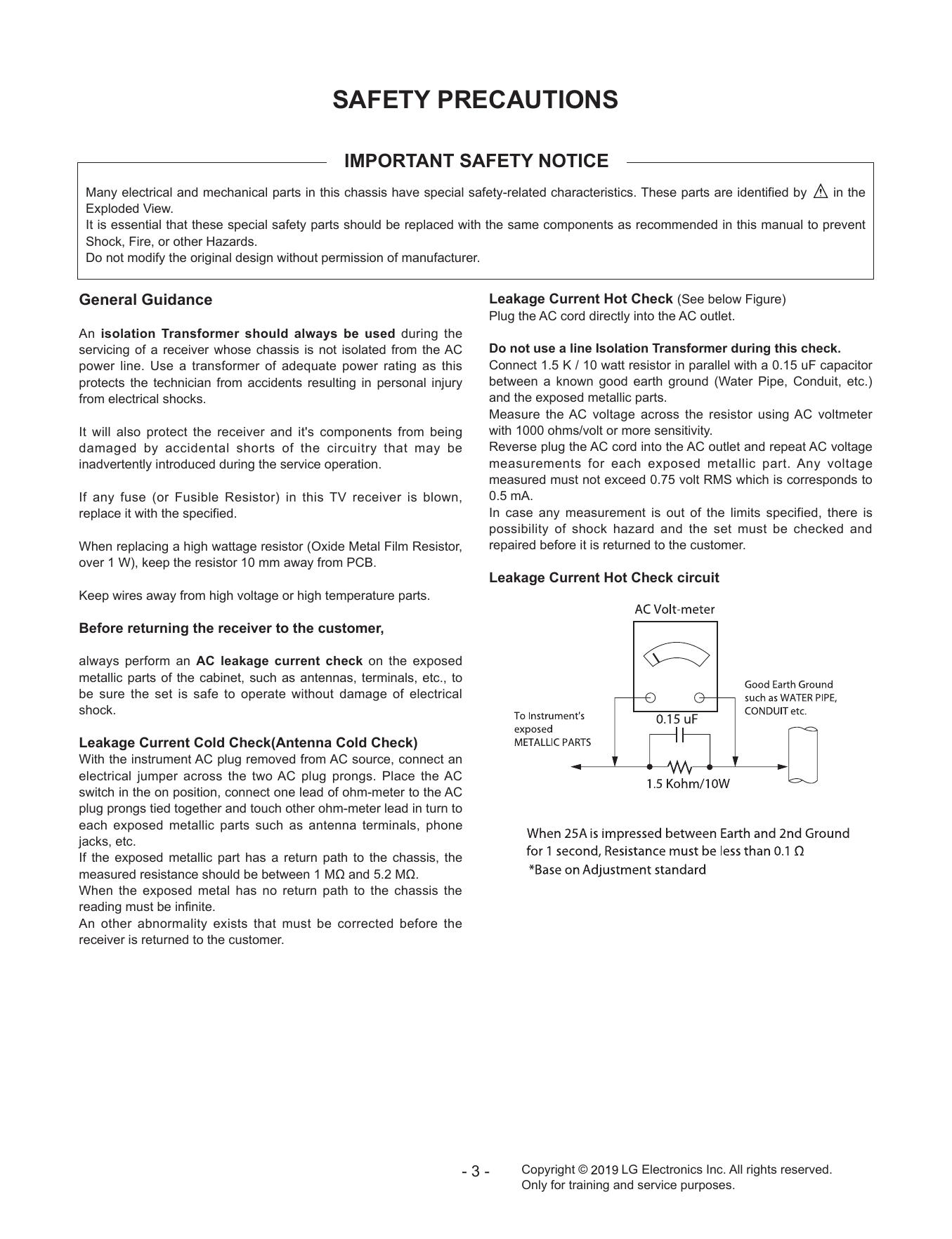
SAFETY PRECAUTIONS
СТРАНИЦА PDF
Страница 4
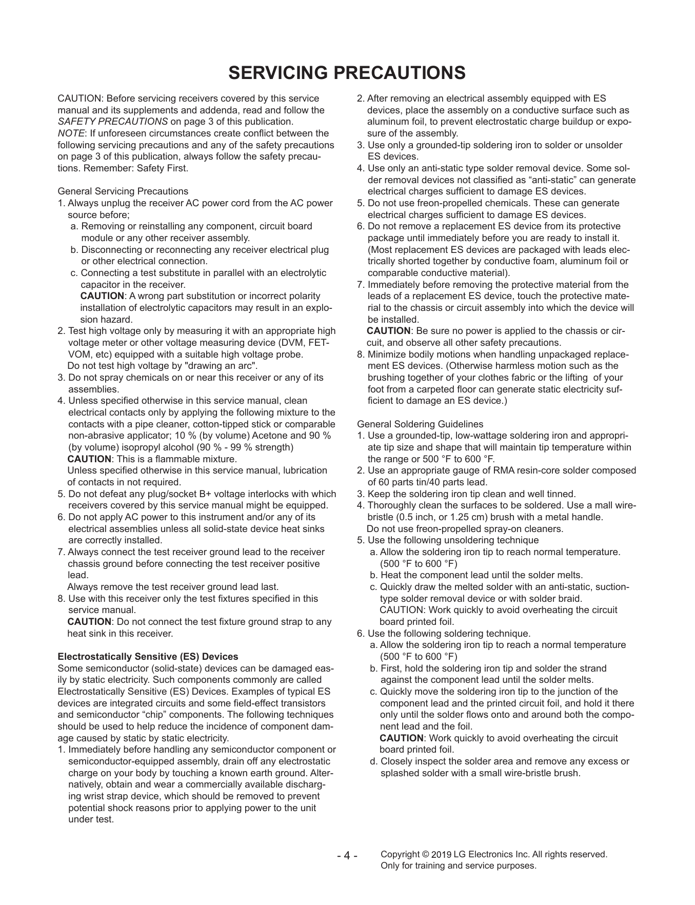
SERVICING PRECAUTIONS
СТРАНИЦА PDF
Страница 5
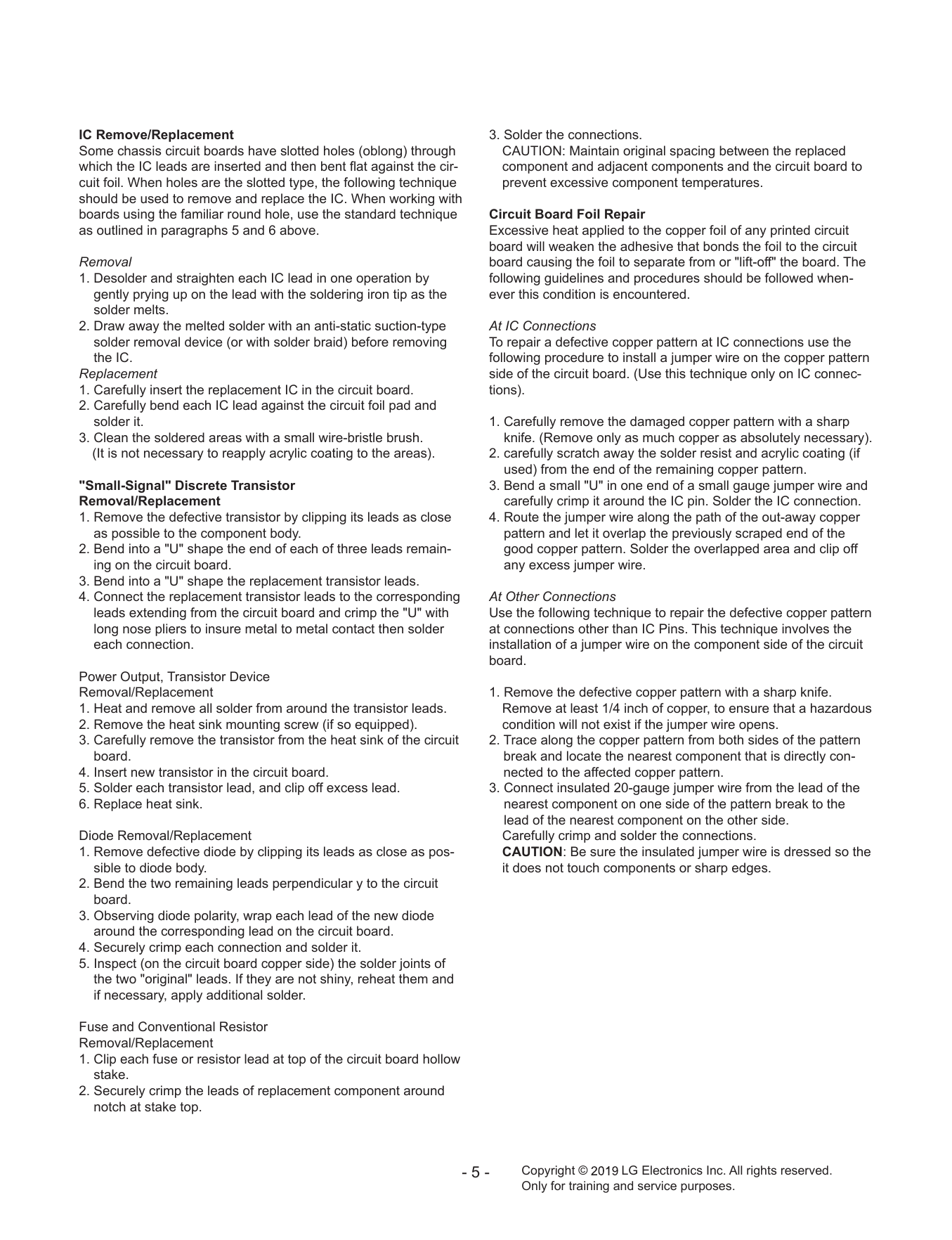
IC Remove/Replacement 3. Solder the connections.
СТРАНИЦА PDF
Страница 6
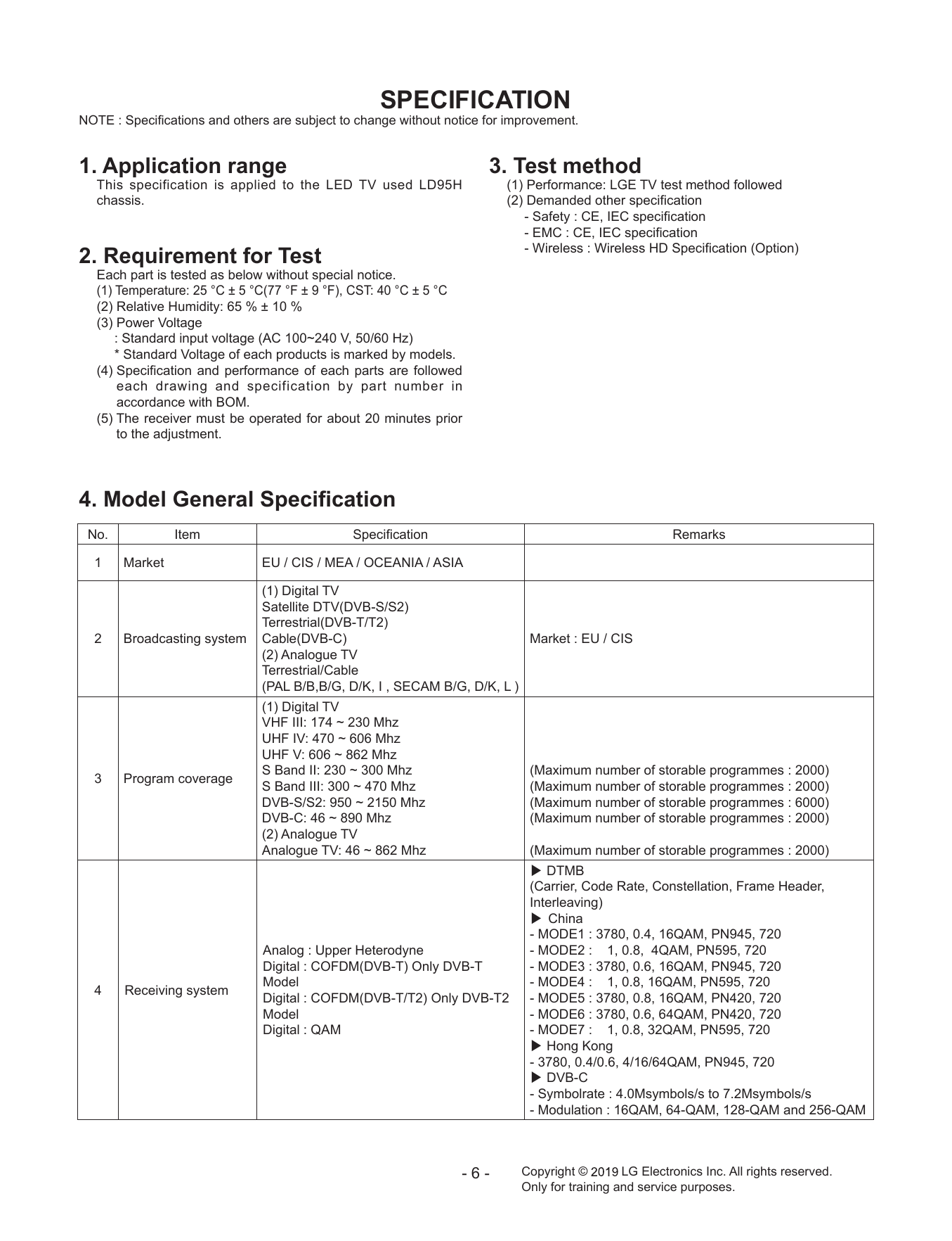
SPECIFICATION
СТРАНИЦА PDF
Страница 7
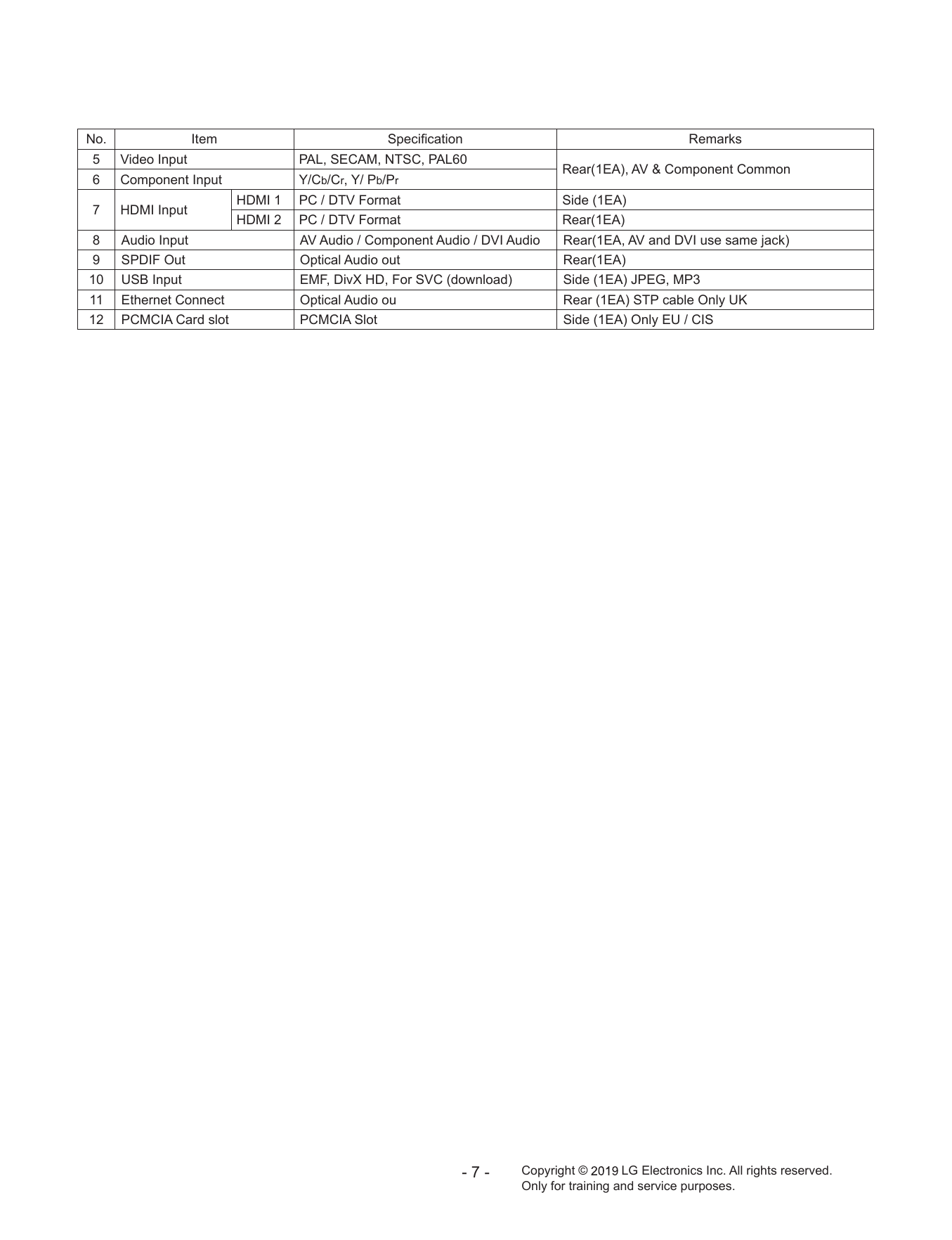
No. Item Specification Remarks
СТРАНИЦА PDF
Страница 8
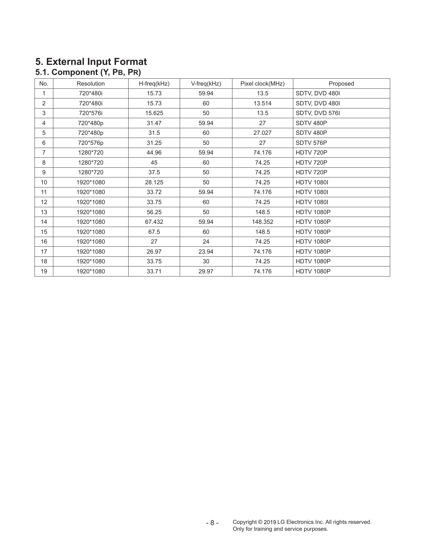
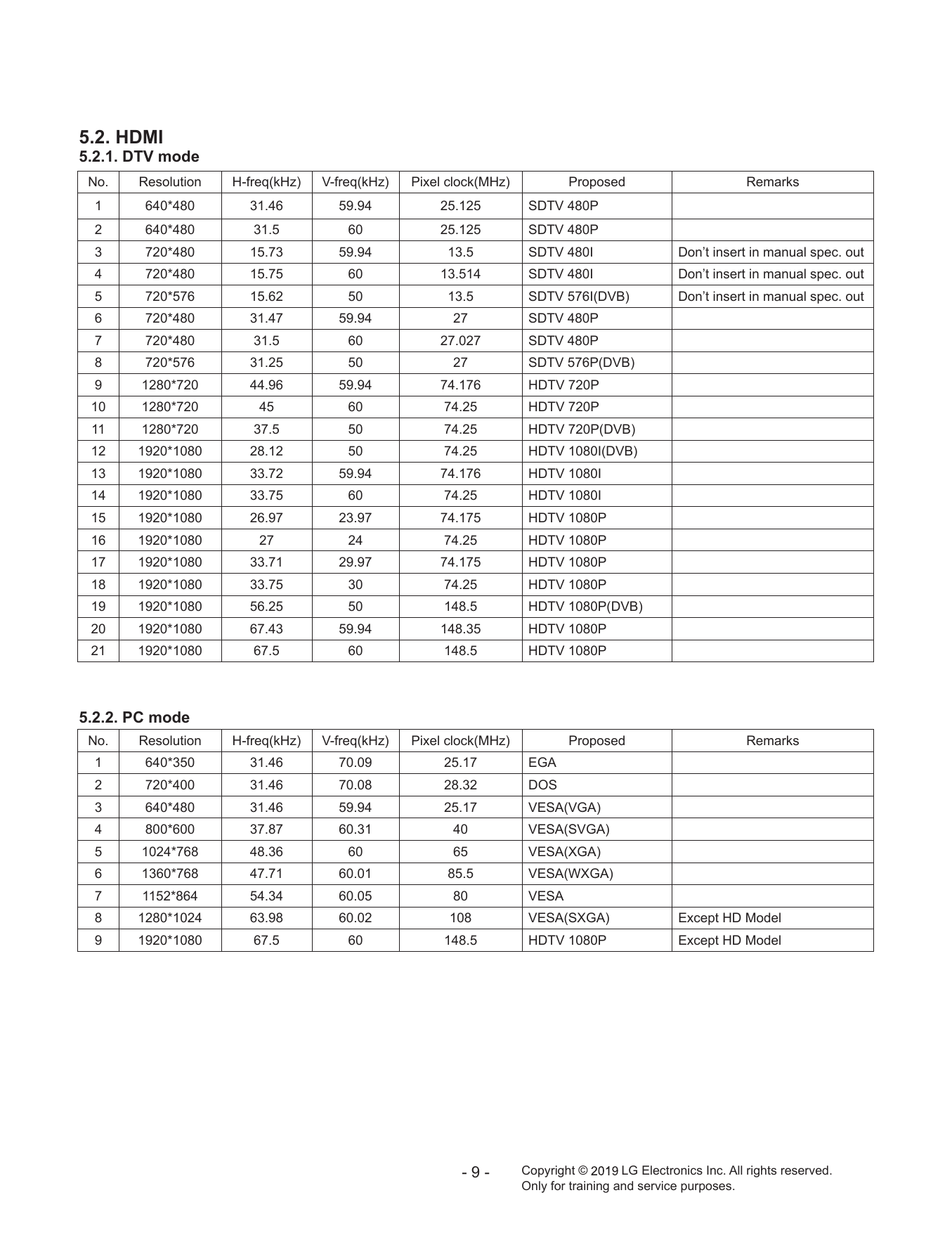
5. External Input Format
СТРАНИЦА PDF
Страница 9
5.2. HDMI
СТРАНИЦА PDF
Страница 10
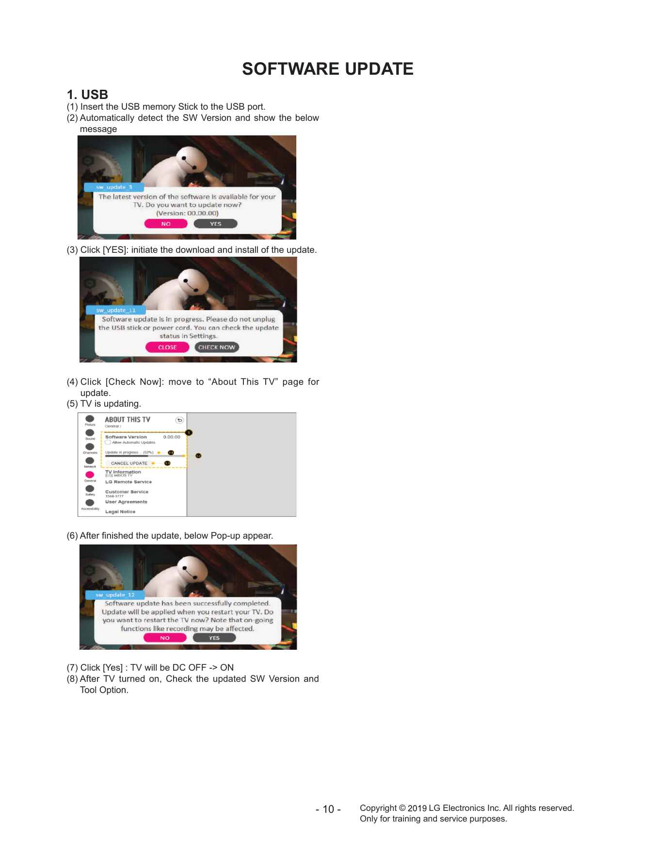
SOFTWARE UPDATE
СТРАНИЦА PDF
Страница 11
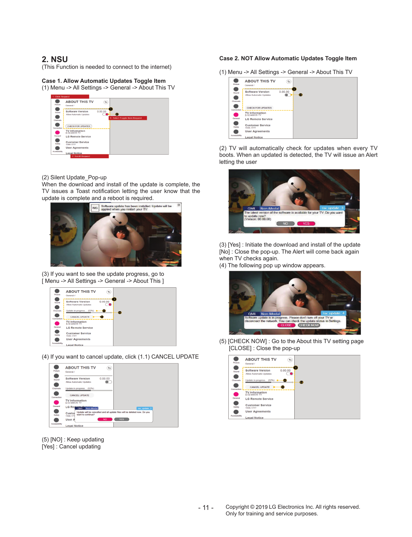
2. NSU Case 2. NOT Allow Automatic Updates Toggle Item
СТРАНИЦА PDF
Страница 12
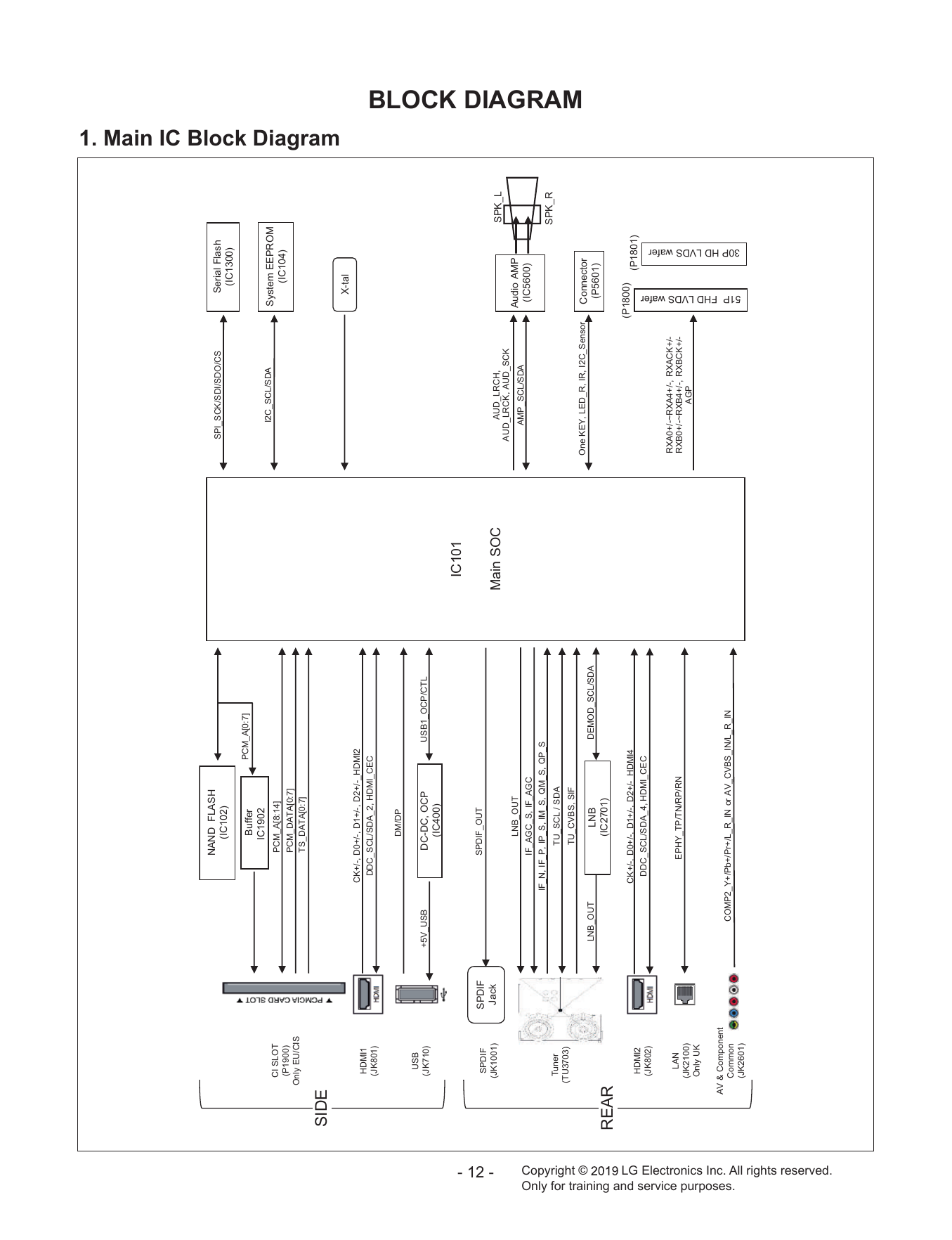
NAND FLASH
CONFIDENTIAL
LED TV
SERVICE MANUAL
CHASSIS : LD95H
MODEL : 43LM5500PLA
CAUTION
BEFORE SERVICING THE CHASSIS, READ THE SAFETY PRECAUTIONS IN THIS MANUAL.
P/NO : MFL71481202 (1903-REV00)
Copyright © 2019 LG Electronics Inc. All rights reserved. Only training and service purposes.
15Y 16Y 15Y
(LF/UF Series) (OLED B6) (OLED)
28Pin 24Pin 24Pin 24Pin NC
18 Marking check 24Pin
18Pin 16Y
New JIG (OLED)
24Pin
13Y/14Y 28Pin
No Marking
OLD JIG
17/18Y
/19Y
17Y/18Y/19Y
W7 (OLED)
24Pin 12Y 18Y/19Y
18Y/19Y
LK57,32/43/49LK54
B8, C8
E8, G8 24Pin
UK63/UK64 32LK61/32LK62 W8
UK65/UK68 43/49LK61 B9/C9/
UK7050 LM57/LM63 E9/W9
18Y/19Y UM73/UM74
SK80/UK89 UM75/UM76/
SK85/SK96 UM79/UM80
16Y/17Y/18Y/19Y
SK95/SK99
SM90/SM98 (UH/UJ/UK/SK/
18Pin /SM
18Y/19Y
24 Marking Check 28Pin UK74,UK75
28Pin 12Pin 12Pin 28Pin
UK77,UK78
Cable Connection SK79
Includes 49UJ63 SM80/SM86
17Y/18Y 16/18Y/19Y 16Y/17Y 16Y
16Y/17Y/18Y/19Y (UH)
(SJ/UJ/UK/SK) (UH/UK/UM) (UH/SJ)
(LH/LJ/LK/LM)
Copyright © 2019 LG Electronics Inc. All rights reserved.
Only for training and service purposes